General Description
The Secure Channel and Message Layer provides a consistent networking service substrate to allow Nodes to communicate securely with one another.
During commissioning and unicast communication, a discovery mechanism is provided to determine peer IPv6 addresses and operational parameters. Secure session establishment mechanisms are provided using either certificates (CASE) or shared passcodes (PASE).
Messages
Communication is performed using messages. Messages are either secured or unsecured.
Each message has a Session Type and Session ID in order to identify whether it is secured and how it is to be decrypted and authenticated if it is. Each message has a Message Counter field in order to uniquely identify the message for the purposes of security and duplicate detection.
Operational communication is defined as traffic that uses the secured Matter message format between commissioned nodes over an IP transport. All operational communication has message security enabled. Operational communication between Nodes can be either unicast or multicast.
Unsecured communication is strictly limited to:
Discovery, which does not use the Matter message format.
User Directed Commissioning (UDC), which uses unsecured messages to initiate the commissioning process.
Session establishment, which uses unsecured messages to establish a CASE or PASE session.
Message Types
Messages are defined as either a control message or data message. Most messages are data messages. Control messages are reserved for internal protocols such as MCSP to initialize security. Both message types are identical in format, but use separate message counter domains so they can operate securely over the same security key.
Message Transports
Messages are of finite size and are sent as individual packets over the supported transports:
UDP transports each message as a separate datagram. Messages support a basic reliability protocol called MRP for use when the underlying transport (in this case UDP) doesn’t provide such features.
TCP transports each message with a length prepended, performing segmentation and reassembly as needed.
BTP transports each message over BLE as a separate SDU, performing segmentation and
reassembly as needed.
BTP is provided as a transport protocol for commissioning. TCP and MRP (UDP with added reliability) are provided as transport protocols for operational messaging.
Message Exchanges
Messages provide an Exchange Layer to track related messages that make up small, discrete transactions. The Exchange Layer provides this transaction tracking facility to the Interaction Model Layer above, providing a means to multiplex multiple such concurrent transactions over a given underlying session. The Exchange Layer also integrates the Message Reliability Protocol (MRP) as a service for use over UDP transports. This Message Layer architecture is shown below in Figure 6, “Message Layer Stack”:
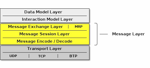
Figure 6. Message Layer Stack
IPv6 Reachability
This section describes IPv6 network configuration requirements to enable IPv6 reachability between Nodes. As described in Section 2.3, “Network Topology”, a Matter network may be composed of one or more IPv6 networks.
In a single network configuration, all Matter Nodes are attached to the same IPv6 link. A single network configuration may consist of a single bridged Wi-Fi / Ethernet network where all nodes attached to that network are part of the same broadcast domain. When all Matter Nodes are attached to the same Wi-Fi / Ethernet network, link-local IPv6 addressing is sufficient - no additional IPv6 network infrastructure is required.
In a multiple network configuration, a Matter network is composed of (typically one) infrastructure network and one or more stub networks. Unlike an infrastructure network, stub networks do not serve as transit networks. Typically, the infrastructure network is a bridged Wi-Fi / Ethernet network and the Thread networks are stub networks. A stub router connects a stub network to an infrastructure network and provides IPv6 reachability between the two networks.
Stub Router Behavior
A stub router SHALL implement [draft-lemon-stub-networks]. In a multiple network configuration, both the infrastructure and stub networks require routable IPv6 addresses to communicate across networks. A routable IPv6 address SHALL have global scope (e.g. GUA or ULA) [RFC 4007] and SHALL be constructed out of a prefix advertised as on-link. If there is no routable prefix on a given network, the stub router SHALL provide its own routable prefix. Note that Thread’s "on-mesh prefix" is equivalent to Wi-Fi / Ethernet’s "on-link prefix".
Stub routers SHALL advertise reachability to all routable prefixes on the adjacent network. A stub router connecting a Thread network SHALL advertise reachability to all of the Thread network’s routable prefixes to the adjacent infrastructure network using Route Information Options [RFC 4191] contained in Router Advertisements [RFC 4861]. That same stub router SHALL also advertise reachability to all of the infrastructure network’s routable prefixes to the adjacent Thread network in the Thread Network Data [Thread specification].
Matter Node Behavior
Matter Nodes SHALL configure a link-local IPv6 address. In addition, Nodes SHALL support configuration of at least three routable IPv6 addresses (in addition to the link-local and, in the case of Thread, mesh-local addresses). On a Wi-Fi / Ethernet interface, ICMPv6 Router Advertisement (RA) messages advertise prefixes for use on the link [RFC 4861]. On a Thread interface, the Thread Network Data contains prefixes for use on the link [Thread specification]. If a Node receives an on- link prefix that allows autonomous configuration on a given interface and the Node has fewer than three routable IPv6 addresses configured, the Node SHALL autonomously configure an IPv6 address out of that prefix.
Matter Nodes SHALL also configure routes to adjacent networks. On Wi-Fi / Ethernet networks, Nodes SHALL process Route Information Options [RFC 4191] and configure routes to IPv6 prefixes assigned to stub networks via stub routers. Wi-Fi / Ethernet interfaces SHALL support maintaining at least 16 different routes configured using Route Information Options. On Thread networks, Nodes SHALL route according to routing information provided in the Thread Network Data [Thread specification]. Thread devices SHALL support as many routes as can be encoded in the Thread Network Data.
Matter Nodes SHALL support a number of IPv6 neighbor cache entries at least as large as the number of supported CASE sessions plus the number of supported routes.
Discovery
This section describes Service Advertising and Discovery for Matter.
Service Advertising and Discovery is used within Matter in the following contexts:
Commissionable Node Discovery
Operational Discovery
Commissioner Discovery
User Directed Commissioning
Service Advertising and Discovery for Matter uses IETF Standard DNS-Based Service Discovery (DNS‑SD) [RFC 6763]. Matter requires no modifications to IETF Standard DNS‑SD.
Using DNS‑SD means that both the unicast IPv6 address and port of the offered service are discovered, freeing Matter from requiring a single preallocated fixed port. This also makes it possible to run multiple instances of Matter software on a single device, because each instance has its own dynamically allocated port, instead of conflicting over attempting to use the same preallocated fixed port.
On Wi‑Fi and Ethernet networks today, DNS‑SD [RFC 6763] uses Multicast DNS [RFC 6762] for zero- configuration operation.
Since Matter protocols must support IPv6 at a minimum, Matter software discovering other Matter instances SHALL process DNS AAAA (IPv6 address) records, but also MAY process DNS A (IPv4 address) records.
Because of this, where feasible in the underlying service discovery API, Matter software advertising the availability of a service SHOULD indicate that announcements and answers for this service need include only IPv6 address records, not IPv4 address records. On a general-purpose dual-stack host that supports both IPv4 and IPv6, this can be achieved by having Matter-related SRV records reference a Matter-specific target hostname that has only IPv6 address records attached. This allows a general-purpose dual-stack host to offer discoverable IPv4 addresses for legacy client software that still requires IPv4, while offering optimized IPv6-only address discovery for Matter purposes.
Similarly, since Matter does not use IPv4, Matter software discovering other Matter instances SHOULD NOT expect any IPv4 addresses included in responses.
These two items address the content of service discovery messages. When using Multicast DNS similar efficiency questions arise related to the delivery of those service discovery messages, sent over IPv4, IPv6, or both.
Where supported in the underlying service discovery API, Matter software using Multicast DNS to advertise the availability of a service SHOULD indicate that announcements and answers for this service need only be performed over IPv6.
Similarly, where supported in the underlying service discovery API, Matter application software using Multicast DNS to issue service discovery queries SHOULD indicate that these queries need only be performed over IPv6.
These optimizations reduce both the size and the number of multicast packets, which is particularly beneficial on Wi‑Fi networks. A Matter device that only supports IPv6 gets these optimizations automatically, simply by virtue of not supporting IPv4 at all.
For Thread mesh networks, where excessive use of multicast would be detrimental [RFC 7558], DNS‑SD uses Unicast DNS instead, leveraging capabilities of the Thread Service Registry on the Thread Border Router [draft-lemon-stub-networks].
Conceptually, the DNS‑SD [RFC 6763] information being communicated is identical to when Multicast DNS [RFC 6762] is being used, except that the information is communicated in unicast
packets to and from a designated Service Registry, rather than being communicated in multicast packets to and from every other node in the same broadcast domain.
Using Service Registration Protocol [SRP] and an Advertising Proxy [AdProx] running on the Thread Border Router, Matter Nodes on a Thread mesh can be discovered by other Matter Nodes on an adjacent Ethernet or Wi‑Fi link, without the cost of using multicast on the Thread mesh. All Thread- connected Matter Nodes SHALL implement Service Registration Protocol.
Thread Border Routers advertise available SRP servers in the Thread Network Data [Thread specification]. Thread devices SHALL register their services using an available SRP server [Thread specification].
When Matter Nodes issue short-lived requests to other Matter Nodes, the response is sent back to the source IPv6 address and port of the request. When Matter Nodes issue long-lived requests to other Matter Nodes, by the time the response is generated the requester may have changed IPv6 address or port, so the responder may have to discover the current IPv6 address and port of the initiator in order to send the response.
A Thread Border Router SHALL implement DNS‑SD Discovery Proxy [RFC 8766] to enable clients on the Thread mesh (e.g., other Nodes) to discover services (e.g., Matter Nodes) advertised using Multicast DNS on an adjacent Ethernet or Wi‑Fi link, also without the cost of using multicast on the Thread mesh [draft-lemon-stub-networks]. For short-lived instantaneous queries, these queries can be performed using unicast DNS over UDP to the DNS‑SD Discovery Proxy. For long-lived queries with ongoing change notification, DNS Push Notifications [RFC 8765] with DNS Stateful Operations [RFC 8490] allows clients on the Thread mesh to be notified of changes to the set of discovered services without expensive polling.
In principle, the Thread mesh Service Registry can be run on any capable Node(s) within (or even outside) the Thread mesh, though in practice the Thread Border Router is an attractive candidate to offer the Service Registry. Thread Border Router devices are typically AC-powered, and typically have more capable CPUs with greater flash storage and RAM than more constrained battery- powered Thread Nodes. Matter devices on Thread are dependent on Thread providing reliable service for those Thread devices on the Thread mesh. This is similar to how Matter devices on Wi‑Fi are dependent on the Wi‑Fi access point (AP) providing reliable service for those Wi‑Fi devices using that Wi‑Fi access point.
Commissionable Node Discovery
The Matter protocol family supports UDP and TCP for Matter commissioning of Commissionees already on the customer’s IP network (such as Ethernet-connected Nodes, or Wi‑Fi Nodes already associated to the Wi‑Fi network via other means), and for the commissioning of Commissionees in conjunction with Wi‑Fi Soft-AP (for Wi‑Fi Nodes not already on the customer’s IP network, when the Node does not support Matter commissioning using BLE).
For these Commissionees, Matter Commissionable Node Discovery is performed using IETF Standard DNS-Based Service Discovery (DNS‑SD) [RFC 6763] as described below.
For Matter Commissionable Node Discovery in the already-on-network and Soft-AP cases, the DNS‑SD instance name SHALL be a dynamic, pseudo-randomly selected, 64-bit temporary unique
identifier, expressed as a fixed-length sixteen-character hexadecimal string, encoded as ASCII (UTF-
8) text using capital letters, e.g., DD200C20D25AE5F7. A new instance name SHALL be selected when the Node boots. A new instance name SHALL be selected whenever the Node enters Commissioning mode. A new instance name MAY be selected at other times, as long as the instance name does not change while the Node is in commissioning mode.
When a Node receives either the OpenCommissioningWindow or the OpenBasicCommissioningWindow command, the Node SHALL only beacon on the IP network using the relevant DNS-SD properties described below.
The Matter Commissionable Node Discovery DNS‑SD instance name SHALL be unique within the namespace of the local network (the .local link-local namespace of the Ethernet and Wi‑Fi links [RFC 6762], or the unicast domain selected by the Thread Border Router for devices on the Thread mesh).
In the rare event of a collision in the selection of the 64-bit temporary unique identifier, the existing DNS‑SD name conflict detection mechanism will detect this collision, and a new pseudo-randomly selected 64-bit temporary unique identifier SHALL be generated by the Matter Commissionee that is preparing for commissioning. Name conflict detection is described in Section 9 ("Conflict Resolution") of the Multicast DNS specification [RFC 6762] and Section 2.4.3.1 ("Validation of Adds") of the Service Registration Protocol specification [SRP].
The DNS‑SD service type [RFC 6335] for Matter Commissionable Node Discovery is _matterc._udp.
For link-local Multicast DNS the service domain SHALL be local. For Unicast DNS such as used on Thread the service domain SHALL be as configured automatically by the Thread Border Router.
Host Name Construction
For DNS‑SD a target host name is required, in addition to the instance name. The target host name SHALL be constructed using one of the available link-layer addresses, such as a 48-bit device MAC address (for Ethernet and Wi‑Fi) or a 64-bit MAC Extended Address (for Thread) expressed as a fixed-length twelve-character (or sixteen-character) hexadecimal string, encoded as ASCII (UTF-8) text using capital letters, e.g., B75AFB458ECD.<domain>. In the event that a device performs MAC address randomization for privacy, then the target host name SHALL use the privacy-preserving randomized version and the hostname SHALL be updated in the record every time the underlying link-layer address rotates. Note that it is legal to reuse the same hostname on more than one interface, even if the underlying link-layer address does not match the hostname on that interface, since the goal of using a link-layer address is to ensure local uniqueness of the generated hostname. If future link layers are supported by Matter that do not use 48-bit MAC addresses or 64-bit MAC Extended Address identifiers, then a similar rule will be defined for those technologies.
Extended Discovery
A Matter Commissionee that advertises Commissionable Node Discovery service records is not necessarily in a state that will allow Commissioning (this state is referred to below as "in Commissioning Mode"). While Section 5.4.2.3, “Announcement Duration” is limited for some forms of device advertisement, a Matter device MAY advertise Matter Commissionable Node Discovery service records for longer periods, possibly permanently. Advertising Commissionable Node
Discovery when not in Commissioning Mode is referred to here as Extended Discovery. Extended Discovery is allowed only for DNS-SD advertisements and not for the other forms of Device Discovery such as BLE Commissioning Discovery and Wi-Fi Temporary Access Point Commissioning Discovery.
To protect customer privacy on public networks, a Matter Commissionee SHALL provide a way for the customer to set a timeout on Extended Discovery, or otherwise disable Extended Discovery. The default behavior for Commissionable Node Discovery SHOULD default to limiting announcement as defined in Section 5.4.2.3, “Announcement Duration” unless the Manufacturer wishes to enable longer periods for specific use cases.
Commissioning Subtypes
The following subtypes for Matter Commissionable Node Discovery are defined:
_L<dddd>, where <dddd> provides the full 12-bit discriminator, encoded as a variable-length decimal number in ASCII text, omitting any leading zeroes.
_S<dd>, where <dd> provides the upper 4 bits of the discriminator, encoded as a variable-length decimal number in ASCII text, omitting any leading zeroes.
_V<ddddd>, where <ddddd> provides the 16-bit Vendor ID, encoded as a variable-length decimal number in ASCII text, omitting any leading zeroes.
_T<ddd>, where <ddd> provides the device type identifier for the device, encoded as a variable- length decimal number in ASCII (UTF-8) text, omitting any leading zeroes. In case the device combines multiple device types, the manufacturer SHOULD choose the device type identifier of the primary function of the device for which the device wishes to be discoverable.
_CM, which represents "currently in Commissioning Mode" (due to any method, for example, a factory new device that has just been put into commissioning mode by the user, or an already- commissioned device which has just received the Open Commissioning Window command).
The long discriminator subtype (e.g., _L840) enables filtering of results to find only Commissionees that match the full discriminator code, as provided in the onboarding payload.
The short discriminator subtype (e.g., _S3) enables filtering of results to find only Commissionees that match the upper 4 bits of the discriminator code, as provided in the manual pairing code.
The optional Vendor ID subtype (e.g., _V123) enables a vendor-specific app to achieve filtering of results to find only Nodes that match that Vendor ID.
The Commissioning Mode subtype (e.g., _CM) enables filtering of results to find only Nodes that are currently in Commissioning Mode. Note that the subtype is _CM regardless of whether the TXT record for commissioning mode is set to 1 (CM=1) or 2 (CM=2). A Commissionee that is not in commissioning mode (CM=0) SHALL NOT publish this subtype.
The optional device type subtype (e.g., _T10) enables filtering of results to find only Nodes that match the device type, generally used for the User-Initiated Beacon Detection, Not Yet Commissioned Device and the User-Initiated Beacon Detection, Already Commissioned Device use cases.
In the event that a vendor-specific app wishes to show the user only some of that vendor’s
Commissionees awaiting commissioning but not all of them, any desired filtering logic (based upon arbitrary criteria, not only Product ID) MAY be implemented within that vendor’s proprietary commissioning app.
TXT Records
After discovery, IPv6 addresses are returned in the AAAA records and key/value pairs are returned in the DNS‑SD TXT record.
Nodes SHALL publish AAAA records for all available IPv6 addresses upon which they are willing to accept Matter commissioning messages.
TXT records available for Commissionable Node Discovery include the common TXT record key/value pairs defined in Section 4.3.4, “Common TXT Key/Value Pairs”.
Commissioners SHALL silently ignore TXT record keys that they do not recognize. This is to facilitate future evolution of this specification without breaking backwards compatibility with existing Commissioners that do not implement the new functionality.
The following subsections describe key/value pairs that are defined specifically for Commissionable Node discovery.
TXT key for discriminator (D)
The key D SHALL provide the full 12-bit discriminator for the Commissionable Node and SHALL be present in the DNS-SD TXT record.
The discriminator value SHALL be encoded as a variable-length decimal number in ASCII text, with up to four digits, omitting any leading zeroes.
Any key D with a value mismatching the aforementioned format SHALL be silently ignored.
As an example, value D=840 would indicate that this Commissionable Node has decimal long discriminator 840. When needed, the upper 4 bits of the discriminator provided by the manual pairing code can be algorithmically derived from the full discriminator.
TXT key for Vendor ID and Product ID (VP)
The optional key VP, if present, MAY provide Vendor ID and Product ID information of the device. A vendor MAY choose not to include it at all, for privacy reasons.
If the VP key is present then it MAY take two forms:
VP=123 gives Vendor ID
VP=123+456 gives Vendor ID + Product ID
The Vendor ID and Product ID SHALL both be expressed as variable-length decimal numbers, encoded as ASCII text, omitting any leading zeroes, and of maximum length of 5 characters each to fit their 16-bit numerical range.
If the Product ID is present, it SHALL be separated from the Vendor ID using a ‘+’ character.
If the VP key is present without a Product ID, the value SHALL contain only the Vendor ID alone, with no ‘+’ character.
If the VP key is present, the value SHALL contain at least the Vendor ID. If the VP key is present, it SHALL NOT have a missing or empty value.
TXT key for commissioning mode (CM)
The key CM (Commissioning Mode) SHALL indicate whether or not the publisher of the record is currently in Commissioning Mode and available for immediate commissioning. When in commissioning mode, the value associated with the CM key indicates the source of the passcode.
Four situations are legal:
The absence of key CM SHALL imply a value of 0 (CM=0).
The key/value pair CM=0 SHALL indicate that the publisher is not currently in Commissioning Mode.
The key/value pair CM=1 SHALL indicate that the publisher is currently in Commissioning Mode and requires use of a passcode for commissioning provided by the Commissionee (e.g., printed on a label or displayed on screen), such as when the device is in a factory-new state or when the Open Basic Commissioning Window command has been used to enter commissioning mode.
The key/value pair CM=2 SHALL indicate that the publisher is currently in Commissioning Mode and requires use of a dynamically generated passcode for commissioning corresponding to the verifier that was passed to the device using the Open Commissioning Window command.
A key value of 2 MAY be used to disambiguate collisions of discriminators between uncommissioned Nodes and commissioned Nodes announcing after a commissioning window was opened. A key value of 2 serves as a hint to Commissioners to possibly expect multiple Nodes with the same discriminator (see Commissioning Discriminator), and to instruct the user to enter the Onboarding Payload presented by another Administrator rather than a code provided by the Commissionee.
Since Extended Discovery can be disabled by the customer, a key value of 0 may not ever be returned by a publisher. When Extended Discovery is disabled and the publisher is not in commissioning mode, then the publisher will not respond to Commissionable Node Discovery.
TXT key for device type (DT)
The optional key DT MAY provide the publisher’s primary device type (see Section 11.23.5.3, “DeviceTypeID”). In case the device combines multiple device types, the manufacturer SHOULD choose the device type identifier of the primary function of the device for which the device wishes to be discoverable. If present, it SHALL be encoded as a variable-length decimal number in ASCII text, omitting any leading zeroes.
For example, the DT=10 key/value pair would indicate that the primary device type is 10 (0x000a), which is the device type identifier for a Door Lock.
TXT key for device name (DN)
The optional key DN MAY provide a device advertisement name. If present, it SHALL be encoded as a valid UTF-8 string with a maximum length of 32 bytes (matching the maximum length of the NodeLabel string in the Basic Information Cluster).
When provided, the source of this value SHALL be editable by the user with use clearly designated as being for on-network advertising and MAY be the value stored in the NodeLabel attribute of the Basic Information Cluster) of the Node.
To protect customer privacy on public networks, if a Commissionee supports this key/value pair, then the Commissionee SHALL provide a way for the customer to disable its inclusion.
A Commissionee SHOULD NOT include this field unless doing so for specific use cases which call for it.
For example, the DN=Living Room key/value pair indicates that the advertisement name specified by the user is 'Living Room'.
TXT key for rotating device identifier (RI)
The optional key RI MAY provide a Rotating Device Identifier.
If present, the value associated with the RI key SHALL contain the octets of the Rotating Device Identifier octet string encoded as the concatenation of each octet’s value as a 2-digit uppercase hexadecimal number.
The resulting ASCII string SHALL NOT be longer than 100 characters, which implies a Rotating Device Identifier of at most 50 octets.
TXT key for pairing hint (PH)
The optional key PH MAY provide a pairing hint.
If present, it SHALL be encoded as a variable-length decimal number in ASCII text, omitting any leading zeroes.
The pairing hint represents a base-10 numeric value for a bitmap of methods supported by the Commissionee in its current state for putting it in Commissioning Mode.
For example, the PH=5 key/value pair represents a hint value with bits 0 and 2 are set. This value MAY change during the lifecycle of the device.
For example, a device may have a value with bit 0 (Power Cycle) set and bit 2 (Administrator app) unset when in a factory reset state, and then have a value with bit 0 unset and bit 2 set after it has been Commissioned.
The bitmap of methods is defined in Table 6, “Pairing Hint Values”.
If the Commissionee has enabled Extended Discovery, then it SHALL include the key/value pair for
PH in the DNS‑SD TXT record when not in Commissioning Mode (CM=0).
This key/value pair MAY be returned when in Commissioning Mode (CM=1).
If the Commissioner does not recognize this value, for example, if the value indicates bit indices defined in a newer version of this specification than the version which the Commissioner implements, then the Commissioner MAY utilize the bits that it does understand and MAY utilize additional data sets available for assisting the user. For example, when a Vendor ID and Product ID are available to the Commissioner, the Section 11.23, “Distributed Compliance Ledger” may also provide a URL for the Device User Guide which can contain additional information to help in Commissioning this Commissionee.
Some of the pairing hints MAY require additional information to be encoded for proper expression of their meaning. This is accomplished with the PI TXT key, described in a following section. Dependency on usage of the PI key is expressed by the PI Dependency column in the table below.
The following fields in the bitmap are currently defined for values of the PH key:
Table 6. Pairing Hint Values
Bit index
Name
PI Dependency
Description
0
Power Cycle
False
The Device will automatically enter Commissioning Mode upon power cycle (unplug/re-plug, remove/re-insert batteries). This bit SHALL be set to 1 for devices using Standard Commissioning Flow, and set to 0 otherwise.
Bit index
Name
PI Dependency
Description
1
Device Manufacturer URL
False
This SHALL be set to 1 for devices requiring Custom Commissioning Flow before they can be available for Commissioning by any Commissioner. For such a flow, the user SHOULD be sent to the URL specified in the
CommissioningCustomFlo
wUrl of the DeviceModel schema entry indexed by the Vendor ID and Product ID (e.g., as found in the announcement) in the Distributed Compliance Ledger.
2
Administrator
False
The Device has been commissioned. Any Administrator that commissioned the device provides a user interface that may be used to put the device into Commissioning Mode.
3
Settings menu on the Node
False
The settings menu on the Device provides instructions to put it into Commissioning Mode.
4
Custom Instruction
True
The PI key/value pair describes a custom way to put the Device into Commissioning Mode. This Custom Instruction option is NOT recommended for use by a Device that does not have knowledge of the user’s language preference.
Bit index
Name
PI Dependency
Description
5
Device Manual
False
The Device Manual provides special instructions to put the Device into Commissioning Mode (see Section 11.23.5.8, “UserManualUrl”). This is a catch-all option to capture user interactions that are not codified by other options in this table.
6
Press Reset Button
False
The Device will enter Commissioning Mode when reset button is pressed.
7
Press Reset Button with application of power
False
The Device will enter Commissioning Mode when reset button is pressed when applying power to it.
8
Press Reset Button for N seconds
True
The Device will enter Commissioning Mode when reset button is pressed for N seconds. The exact value of N SHALL be made available via PI key.
9
Press Reset Button until light blinks
True
The Device will enter Commissioning Mode when reset button is pressed until associated light blinks.
Information on color of light MAY be made available via PI key (see Note 1).
Bit index
Name
PI Dependency
Description
10
Press Reset Button for N seconds with application of power
True
The Device will enter Commissioning Mode when reset button is pressed for N seconds when applying power to it. The exact value of N SHALL be made available via PI key.
11
Press Reset Button until light blinks with application of power
True
The Device will enter Commissioning Mode when reset button is pressed until associated light blinks when applying power to the Device. Information on color of light MAY be made available via PI key (see Note 1).
12
Press Reset Button N times
True
The Device will enter Commissioning Mode when reset button is pressed N times with maximum 1 second between each press. The exact value of N SHALL be made available via PI key.
13
Press Setup Button
False
The Device will enter Commissioning Mode when setup button is pressed.
14
Press Setup Button with application of power
False
The Device will enter Commissioning Mode when setup button is pressed when applying power to it.
15
Press Setup Button for N seconds
True
The Device will enter Commissioning Mode when setup button is pressed for N seconds. The exact value of N SHALL be made available via PI key.
Bit index
Name
PI Dependency
Description
16
Press Setup Button until light blinks
True
The Device will enter Commissioning Mode when setup button is pressed until associated light blinks.
Information on color of light MAY be made available via PI key (see Note 1).
17
Press Setup Button for N seconds with application of power
True
The Device will enter Commissioning Mode when setup button is pressed for N seconds when applying power to it. The exact value of N SHALL be made available via PI key.
18
Press Setup Button until light blinks with application of power
True
The Device will enter Commissioning Mode when setup button is pressed until associated light blinks when applying power to the Device. Information on color of light MAY be made available via PI key (see Note 1).
19
Press Setup Button N times
True
The Device will enter Commissioning Mode when setup button is pressed N times with maximum 1 second between each press. The exact value of N SHALL be made available via PI key.
Note 1: When the PH key indicates a light to blink (one or more of bits 9, 11, 16 or 18 is set), information on color of light MAY be made available via PI key. When using such color indication in PI key, only basic primary and secondary colors that could unambiguously be decoded by a commissioner and understood by an end-user, but without worry of localization, SHOULD be used,
e.g. white, red, green, blue, orange, yellow, purple.
Note 2: Any undefined values are reserved for future use.
Note 3: A Commissionee can indicate multiple ways of being put into Commissioning Mode by setting multiple bits in the bitmap at the same time. However, only one method can be specified which has a dependency on the PI key (PI Dependency=True) at a time.
For example:
A PH value of 33 (bits 0 and 5 are set) indicates that the user can cause the Commissionee to enter Commissioning Mode by either power cycling it or by following special instructions provided in the Device Manual.
A PH value of 9 (bits 0 and 3 are set) indicates that the user can cause the Commissionee to enter Commissioning Mode by either power cycling it or going to the settings menu and following instructions there.
A PH value of 1 (bit 0 is set) indicates that the user can cause the Commissionee to enter Commissioning Mode only by power cycling it.
A PH value of 16 (bit 4 is set) indicates that the user can cause the Commissionee to enter Commissioning Mode following a custom procedure described by the value of the PI key.
A PH value of 256 (bits 8 is set) indicates that the user can cause the Commissionee to enter Commissioning Mode by pressing the reset button for a duration of time in seconds specified via by the value of the PI key.
When the PH key is provided, at least one bit in the above bitmap SHALL be set. That is, a PH value of 0 is undefined and illegal.
When the PH key is provided, the Commissioner SHOULD take its value into account when providing guidance to the user regarding steps required to put the Commissionee into Commissioning Mode.
TXT key for pairing instructions (PI)
The optional key PI MAY give the pairing instruction.
If present, the value SHALL be encoded as a valid UTF-8 string with a maximum length of 128 bytes. The meaning of this key is dependent upon the PH key value, see Table 6, “Pairing Hint Values”.
For example, given PH=256, bit 8 is set which indicates "Press Reset Button for N seconds". Therefore, a value of PI=10 would indicate that N is 10 in that context.
When bit 4 of the value expressed by the PH key is set, indicating presence of a custom string, the Commissionee SHALL be responsible for localization (translation to user’s preferred language) as required using the Device’s currently configured locale. The Custom Instruction option is NOT recommended for use by a Commissionee that does not have knowledge of the user’s language preference.
It is RECOMMENDED to keep the length of PI field small and adhere to the guidance given in section 6.2 of [RFC 6763].
This key/value pair SHALL only be returned in the DNS‑SD TXT record if the PH bitmap value has a bit set which has PI Dependency = True, see Table 6, “Pairing Hint Values”. The PH key SHALL NOT
not have more than one bit set which has a dependency on the PI key (PI Dependency = True) to avoid ambiguity in PI key usage.
Examples
The examples below simulate a Node in commissioning mode advertising its availability for commissioning.
Examples are shown using both the dns-sd command-line test tool and the avahi command-line test tool. The dns-sd command-line test tool is included in all versions of macOS. It is installed as a DOS command with Bonjour for Windows, and is available on Linux by installing the mDNSResponder package. The Avahi package of command line tools is available from the Avahi project for most Linux distributions.
These examples are given for illustrative purposes only. Real Matter Commissionees and Commissioners would not use a command-line test tool for advertising and discovery. Real Matter Commissionees and Commissioners would use the appropriate DNS‑SD APIs in their respective chosen programming languages.

dns-sd -R DD200C20D25AE5F7 _matterc._udp,_S3,_L840,_CM . 11111 D=840 CM=2
Consider a device on Wi-Fi using the 48-bit device MAC address of B75AFB458ECD as its host name and a value of DD200C20D25AE5F7 as its commissionable service instance name. DNS-SD records for it can be set up as follows:

avahi-publish-service --subtype=_S3._sub._matterc._udp
--subtype=_L840._sub._matterc._udp DD200C20D25AE5F7 --subtype=_CM._sub._matterc._udp
_matterc._udp 11111 D=840 CM=2
or
Short discriminator is filterable through _S3 subtype and algorithmically through D=840 TXT key.
Long discriminator is filterable through _L840 subtype and directly through D=840 TXT key.
The Commissionee is currently in Commissioning Mode after an Administrator having opened a commissioning window (see Section 4.3.1.7, “TXT key for commissioning mode (CM)”), as shown by CM=2 TXT key and availability by browsing the _CM subtype.
Had the Commissionee been discoverable for initial commissioning rather than subsequent additional commissioning, a CM=1 TXT key would have been published instead.

avahi-publish-address B75AFB458ECD.local fe80::f515:576f:9783:3f30
Avahi only sends a single AAAA record. To force the link-local address to be used, use avahi- publish-address. For example:
The DNS‑SD service registration commands shown above results in the creation of the following

Multicast DNS records:
_matterc._udp.local.
PTR
DD200C20D25AE5F7._matterc._udp.local.
_S3._sub._matterc._udp.local.
PTR
DD200C20D25AE5F7._matterc._udp.local.
_L840._sub._matterc._udp.local.
PTR
DD200C20D25AE5F7._matterc._udp.local.
_CM._sub._matterc._udp.local.
PTR
DD200C20D25AE5F7._matterc._udp.local.
DD200C20D25AE5F7._matterc._udp.local.
SRV
0 0 11111 B75AFB458ECD.local.
DD200C20D25AE5F7._matterc._udp.local.
TXT
"D=840" "CM=2"
B75AFB458ECD.local.
AAAA
fe80::f515:576f:9783:3f30

dns-sd -R DD200C20D25AE5F7 _matterc._udp,_S3,_L840,_V123,_CM,_T81 . 11111 D=840 VP=123+456 CM=2 DT=81 DN="Kitchen Plug" PH=256 PI=5
Consider a device on Wi-Fi using the 48-bit device MAC address of B75AFB458ECD as its host name. DNS-SD records for it can be set up as follows, when it is in Commissionable Node Discovery.

avahi-publish-service --subtype=_S3._sub._matterc._udp
--subtype=_L840._sub._matterc._udp --subtype=_V123._sub._matterc._udp
--subtype=_CM._sub._matterc._udp --subtype=_T81._sub._matterc._udp DD200C20D25AE5F7
_matterc._udp 11111 D=840 VP=123+456 CM=2 DT=81 DN="Kitchen Plug" PH=256 PI=5
or
Short discriminator is 3, long discriminator is 840.
Vendor ID is 123, Product ID is 456.
Commissioning Mode is 2, indicating the Commissionee is currently in Commissioning Mode due to the Open Commissioning Window command.
Device type is 81 which is a Smart Plug (Device Type Identifier 0x0051).
Device name is Kitchen Plug.
Pairing hint is 256 which indicates that the Commissionee’s reset button must be held down for 5 seconds to enter Commissioning Mode where the value 5 is obtained by reading the value of the PI key.
Pairing instruction is 5.

avahi-publish-address B75AFB458ECD.local fe80::f515:576f:9783:3f30
Avahi only sends a single AAAA record. To force the link-local address to be used, use avahi- publish-address. For example:
The DNS‑SD service registration commands shown above results in the creation of the following Multicast DNS records:
_matterc._udp.local.
PTR
DD200C20D25AE5F7._matterc._udp.local.
_S3._sub._matterc._udp.local.
PTR
DD200C20D25AE5F7._matterc._udp.local.
_L840._sub._matterc._udp.local.
PTR
DD200C20D25AE5F7._matterc._udp.local.
_V123._sub._matterc._udp.local.
PTR
DD200C20D25AE5F7._matterc._udp.local.
_CM._sub._matterc._udp.local.
PTR
DD200C20D25AE5F7._matterc._udp.local.
_T81._sub._matterc._udp.local.
PTR
DD200C20D25AE5F7._matterc._udp.local.
DD200C20D25AE5F7._matterc._udp.local.
TXT
"D=840" "VP=123+456" "CM=1" "DT=81"
"DN=Kitchen Plug" "PH=256" "PI=5"
DD200C20D25AE5F7._matterc._udp.local.
SRV
0 0 11111 B75AFB458ECD.local.
B75AFB458ECD.local.
AAAA
fe80::f515:576f:9783:3f30

The port number 11111 is given here purely as an example. One of the benefits of using DNS‑SD is that services are not constrained to use a single predetermined well-known port. The port, along with the IPv6 address, is discovered by Commissioners at run time.

dns-sd -B _matterc._udp
A Commissioner can discover all available Commissionees awaiting commissioning:

avahi-browse _matterc._udp -r
or

dns-sd -B _matterc._udp,_S3
A Commissioner can discover Commissionees awaiting commissioning with short discriminator 3:

avahi-browse _S3._sub._matterc._udp -r
or

dns-sd -B _matterc._udp,_L840
A Commissioner can discover Commissionees awaiting commissioning with long discriminator 840:

avahi-browse _L840._sub._matterc._udp -r
or
A Commissioner can discover Commissionees awaiting commissioning with Vendor ID 123:

dns-sd -B _matterc._udp,_V123

avahi-browse _V123._sub._matterc._udp -r
or

dns-sd -B _matterc._udp,_CM
A Commissioner can discover all Commissionees in commissioning mode:

avahi-browse _CM._sub._matterc._udp -r
or

dns-sd -B _matterc._udp,_T81
A commissioner can discover Matter Nodes with Device Type 81:

avahi-browse _T81._sub._matterc._udp -r
or

dns-sd -B _matterc._udp,_CM
A Commissioner can discover Nodes that are currently in Commissioning Mode as a result of a commissioning window opened by a current Administrator as a result of invoking either the Open Commissioning Window command or the Open Basic Commissioning Window command, using the presence of the _CM subtype as a browsing filter:

avahi-browse _CM._sub._matterc._udp -r
or
Efficiency Considerations
Discovering and using an offered service on the network typically involves several steps:
Enumeration of instances available on the network ("browsing")
Lookup of a selected instance’s port number, host name, and other additional information, communicated in DNS‑SD using SRV and TXT records ("resolving")
Lookup of the IPv6 address(es) associated with the desired target host.
Use of IPv6 Neighbor Discovery and/or IPv6 routing to translate from destination IPv6 address to the next-hop link-layer address for that communication.
Establishing a cryptographically secure communication channel between the two endpoints, and then engaging in useful communication.
Although the first three steps are exposed in some APIs as separate steps, at a protocol level they usually require only a single network round-trip. When a PTR query is issued to discover service instances, the usual DNS Additional Record mechanism, where packet space permits, automatically places the related SRV, TXT, and address records into the Additional Record section of the reply. These additional records are stored by the client, to enable subsequent steps in the sequence to be performed without additional redundant network operations to learn the same information a second time.
DNS‑SD over Multicast DNS works by receiving replies from other Nodes attached to the same local link, Nodes that may have been previously completely unknown to the requester. Because of this, Multicast DNS, like IPv6 Neighbor Discovery, does not have any easy way to distinguish genuine replies from malicious or fraudulent replies. Consequently, application-layer end-to-end security is essential. Should a malicious device on the same local link give deliberately malicious or fraudulent replies, the misbehavior will be detected when the device is unable to establish a cryptographically secure application-layer communication channel. This reduces the threat to a Denial-of-Service attack, which can be remedied by physically removing the offending device.
Operational Discovery
For Matter Nodes that have already been commissioned onto a Matter Fabric, run-time dynamic discovery of operational Matter Nodes is used, rather than assuming a fixed unchanging IPv6 address and port for the lifetime of the product. This is done to allow for greater flexibility, so that the underlying IPv6 network can grow and evolve over time as needed without breaking Matter functionality. This is the same reason that other networked consumer electronics products do not assume a single fixed unchanging IP address for the lifetime of the product [RFC 5505].
Operational Instance Name
For Matter operational discovery the DNS‑SD instance name is constructed from a 64-bit compressed Fabric identifier, and a 64-bit Node identifier, as assigned by the commissioner, each expressed as a fixed-length sixteen-character hexadecimal string, encoded as ASCII (UTF-8) text using capital letters, separated by a hyphen. For example, a Matter Node with Matter compressed fabric identifier 2906-C908-D115-D362 and Matter Node identifier 8FC7-7724-01CD-0696 has Matter operational discovery DNS‑SD instance name 2906C908D115D362-8FC7772401CD0696.
The Matter operational discovery DNS‑SD instance name needs to be unique within the namespace of the local network (the .local link-local namespace of the Ethernet and Wi‑Fi links [RFC 6762], or the unicast domain selected by the Thread Border Router for devices on the Thread mesh). This uniqueness is assumed to be guaranteed by appropriate selection of a unique Matter fabric identifier and unique Node identifier within that Matter fabric.
Compressed Fabric Identifier

byte CompressedFabricInfo[16] = /* "CompressedFabric" */
{0x43, 0x6f, 0x6d, 0x70, 0x72, 0x65, 0x73, 0x73, 0x65, 0x64, 0x46, 0x61, 0x62, 0x72, 0x69, 0x63}
CompressedFabricIdentifier = Crypto_KDF(
inputKey := TargetOperationalRootPublicKey, salt:= TargetOperationalFabricID,
info := CompressedFabricInfo, len := 64)
In order to reduce the very large size of a full Fabric Reference which would need to be used as the scoping construct in the instance name, a 64-bit compressed version of the full Fabric Reference SHALL be used. The computation of the Compressed Fabric Identifier SHALL be as follows:
Where:
TargetOperationalRootPublicKey is the raw uncompressed elliptical curve public key of the root certificate for the advertised Node’s Operational Certificate chain, without any format marker prefix byte (i.e. after removing the first byte of the ec-pub-key field in the Operational Certificate’s root).
TargetOperationalFabricID is the octet string for the Fabric ID as it appears in the advertised Node’s Operational Certificate's subject field, under the 1.3.6.1.4.1.37244.1.5 RDN, that is, a 64-bit unsigned integer scalar in big-endian byte order.

pub:
04:4a:9f:42:b1:ca:48:40:d3:72:92:bb:c7:f6:a7:e1:
1e:22:20:0c:97:6f:c9:00:db:c9:8a:7a:38:3a:64:1c:
b8:25:4a:2e:56:d4:e2:95:a8:47:94:3b:4e:38:97:c4:
a7:73:e9:30:27:7b:4d:9f:be:de:8a:05:26:86:bf:ac:
fa
For example, if the root public key for a given Operational Certificate chain containing the identity to be advertised were the following:

4a:9f:42:b1:ca:48:40:d3:72:92:bb:c7:f6:a7:e1:1e:
22:20:0c:97:6f:c9:00:db:c9:8a:7a:38:3a:64:1c:b8:
25:4a:2e:56:d4:e2:95:a8:47:94:3b:4e:38:97:c4:a7:
73:e9:30:27:7b:4d:9f:be:de:8a:05:26:86:bf:ac:fa
Then the value for TargetOperationalRootPublicKey to use in the derivation of the compressed Fabric Identifier would be without the leading 04:
If using the above TargetOperationalRootPublicKey and a TargetOperationalFabricID value of 0x2906_C908_D115_D362 (octet string 29:06:c9:08:d1:15:d3:62 in big-endian), then the
CompressedFabricIdentifier to use in advertising would be 87E1B004E235A130 (octet string
87:e1:b0:04:e2:35:a1:30).
Operational Service Type
The DNS‑SD service type [RFC 6335] for Matter Operational Discovery is _matter._tcp. Note that the string _tcp is boilerplate text inherited from the original DNS SRV specification [RFC 2782], and doesn’t necessarily mean that the advertised application-layer protocol runs only over TCP. It is merely mnemonic text which is there to help human readers, and in no way affects software advertising or using the application-layer protocol identified by that unique IANA-recorded service type string.
The following subtype is defined:
1. Compressed Fabric Identifier _I<hhhh>, where <hhhh> is the Compressed Fabric Identifier encoded as exactly 16 uppercase hexadecimal characters, for example _I87E1B004E235A130 for the Compressed Fabric Identifier example of the previous section. This subtype enables filtering of devices per Fabric if service enumeration (browsing) is attempted, to reduce the set of results to Nodes of interest with operational membership in a given Fabric..
Operational Service Domain and Host Name
For link-local Multicast DNS the service domain SHALL be local. For Unicast DNS such as used on Thread the service domain SHALL be as configured automatically by the Thread Border Router.
For DNS‑SD a target host name is required, in addition to the instance name. The target host name SHALL be constructed using one of the available link-layer addresses, such as a 48-bit device MAC address (for Ethernet and Wi‑Fi) or a 64-bit MAC Extended Address (for Thread) expressed as a fixed-length twelve-character (or sixteen-character) hexadecimal string, encoded as ASCII (UTF-8) text using capital letters, e.g., B75AFB458ECD.<domain>. In the event that a device performs MAC address randomization for privacy, then the target host name SHALL use the privacy-preserving randomized version and the hostname SHALL be updated in the record every time the underlying link-layer address rotates. Note that it is legal to reuse the same hostname on more than one interface, even if the underlying link-layer address does not match the hostname on that interface, since the goal of using a link-layer address is to ensure local uniqueness of the generated hostname. If future link layers are supported by Matter that do not use 48-bit MAC addresses or 64-bit MAC Extended Address identifiers, then a similar rule will be defined for those technologies.
Operational Discovery Service Records
After discovery, IPv6 addresses are returned in the AAAA records and key/value pairs are returned in the DNS‑SD TXT record. The TXT record MAY be omitted if no keys are defined.
Nodes SHALL publish AAAA records for all available IPv6 addresses upon which they are willing to accept operational messages.
Only the common TXT record key/value pairs defined in Section 4.3.4, “Common TXT Key/Value Pairs” are defined for use in Operational Discovery.
Nodes SHALL silently ignore TXT record keys that they do not recognize.
Performance Recommendations
To improve overall performance of operational discovery, especially in large installations, the following recommendations SHOULD be taken in account:
Nodes SHOULD cache the last-known IPv6 address and port for each peer Node with which they interact from their SRV record resolved using DNS-SD, to save the cost of a run-time network lookup operation when not needed. When the IPv6 address and port for a peer Node is not known, or an attempt to communicate with a peer Node at its last-known IPv6 address and port does not appear to be succeeding within the expected network round-trip time (i.e., the retransmission timeout value for the first message packet) a Node SHOULD then perform a run- time discovery in parallel, to determine whether the desired Node has acquired a new IPv6 address and/or port [RFC 8305].
Nodes SHOULD respond to nonspecific service enumeration queries for the generic Matter Operational Discovery service type (_matter._tcp), but these queries SHOULD NOT be used in routine operation, and instead it is RECOMMENDED that they only be used for diagnostics purposes or to determine new membership within a fabric. When used, it is RECOMMENDED that service enumeration employ the _I<HHHH> Fabric-specific subtype to only enumerate the desired Nodes on the Fabric of interest in the local network. Moreover, Known Answer Suppression [RFC 6762] SHOULD be employed in such cases to further minimize the number of unnecessary responses to such a query.
When resolving the operational service record of another Node, a Node SHOULD use an SRV query for the desired operational service instance rather than doing general enumeration of all nodes (e.g. PTR query) followed by filtering for the desired service instance. This recommendation reduces the amount of multicast traffic generated on-link when Multicast DNS is used, and reduces latency to successful service resolution.
Since proxied DNS-SD service discovery MAY be in use within a given network, and service record caching is expected of DNS-SD clients, Nodes SHOULD NOT use DNS-SD as an operational liveness determination method. This is because there may be stale records not yet expired after a Node becomes unreachable which may still be available.
Operational Discovery DNS-SD Examples
The example below simulates a commissioned Matter Node advertising its availability for control via the Matter protocol.
Examples are shown using both the dns-sd command-line test tool and the avahi command-line test tool. The dns-sd command-line test tool is included in all versions of macOS. It is installed as a DOS command with Bonjour for Windows, and is available on Linux by installing the mDNSResponder package. The avahi command line-test tool is available from the Avahi project for most Linux distributions.
This example is given for illustrative purposes only. Real Matter Nodes and controllers would not use a command-line test tool for advertising and discovery. Real Matter Nodes and controllers would use the appropriate DNS‑SD APIs in their respective chosen programming languages.
Consider a device on Wi-Fi using the 48-bit device MAC address of B75AFB458ECD as its host name. DNS-SD records for can be set up as follows:

dns-sd -R 87E1B004E235A130-8FC7772401CD0696 _matter._tcp . 22222

avahi-publish-service 87E1B004E235A130-8FC7772401CD0696 _matter._tcp 22222
or
The port number 22222 is given here purely as an example. One of the benefits of using DNS‑SD is that services are not constrained to use a single predetermined well-known port. This means that multiple instances of the Matter Node control service can run on the same device at the same time, listening on different ports [RFC 6760]. The port, along with the IPv6 address, is discovered by the Matter controller at run time.

avahi-publish-address B75AFB458ECD.local fe80::f515:576f:9783:3f30
Avahi only sends a single AAAA record. To force the link-local address to be used, use avahi- publish-address. For example:

dns-sd -L 87E1B004E235A130-8FC7772401CD0696 _matter._tcp 87E1B004E235A130-8FC7772401CD0696._matter._tcp.local. can be reached at B75AFB458ECD.local.:22222
dns-sd -Gv6 B75AFB458ECD.local fe80::f515:576f:9783:3f30
A Matter controller can discover the current IPv6 address and port for a known commissioned Matter Node:

avahi-browse _matter._tcp -r
hostname = [B75AFB458ECD.local] address = [fe80::f515:576f:9783:3f30] port = [22222]
or
Commissioner Discovery
A Commissionee MAY initiate the commissioning process by discovering Commissioners on the network (see Initiating Commissioning from an Existing Device). This MAY be done using Commissioner Discovery described in this section.
With Commissioner Discovery, a Commissionee, upon user interaction, MAY discover Commissioners on the network and obtain a list of information for each which may include Vendor ID, Product ID and friendly name. A Commissionee with a user interface, such as a Television,
Thermostat or Video Player device, MAY display the list of discovered commissioners to the user for selection. Once selected, the Commissionee MAY use the User Directed Commissioning protocol with the Commissioner to indicate that the user has selected it for commissioning of the Commissionee. The Commissioner Discovery service records thus enable a form of "door bell" protocol to allow a Commissionee to request Commissioning.
The Commissioner Discovery feature is optional for both the Commissionee and the Commissioner. Any mandatory requirements described in this section SHALL apply only if the Node or the Commissioner supports this feature. To protect customer privacy on public networks, a Matter Commissioner SHALL provide a way for the customer to set a timeout on Commissioner Discovery, or otherwise disable Commissioner Discovery.
For Commissioner Discovery, the DNS-SD instance name is generated the same way it is done for Commissionable Node Discovery and has the same requirements (uniqueness on local network, and collision detection and recovery) as those in Commissionable Node Discovery, but the requirements for when a new instance name is selected from Commissionable Node Discovery do not apply to Commissioner Discovery. The instance name for Commissioner Discovery MAY be selected whenever the Commissioner deems necessary.
The DNS-SD service type [RFC 6335] is _matterd._udp.
The port advertised by a _matterd._udp service record SHALL be different than any port associated with other advertised _matterc._udp, _matter._tcp or _matterd._udp services, in order to ensure that the session-less messaging employed by the User Directed Commissioning protocol does not cause invalid message handling from fully operational Matter nodes at the same address. In other words, each _matterd._udp service instance needs to be independent from other services to ensure unambiguous processing of the incoming User Directed Commissioning messages.
The following subtype is defined:
\_T<ddd> where <ddd> is the device type identifier (see Data Model Device Types), encoded as a variable-length decimal number in ASCII (UTF-8) text, without leading zeroes. This optional Device Type subtype enables filtering of results to find only Commissioners that match a device type, for example, to discover Commissioners of type Video Player (35 is decimal representation for Video Player device type identifier 0x0023). For such a Video Player filter, subtype _T35 would be used.
For link-local Multicast DNS the service domain SHALL be local. For Unicast DNS such as used on Thread the service domain SHALL be as configured automatically by the Thread Border Router.
The target host name is generated the same way it is done for Commissionable Node Discovery (see Host Name Construction).
After discovery, IPv6 addresses are returned in the AAAA records and key/value pairs are returned in the DNS‑SD TXT record. The TXT record MAY be omitted if no keys are defined.
Nodes SHALL publish AAAA records for all their available IPv6 addresses.
In addition to the common TXT record key/value pairs defined in Section 4.3.4, “Common TXT Key/Value Pairs”, the following key/value pairs are defined specifically for Commissioner discovery:
The optional key VP gives vendor and product information. This key is optional for a vendor to provide, and optional for a commissioner to use. This value takes the same format described for the VP key in Commissionable Node Discovery (see Section 4.3.1.6, “TXT key for Vendor ID and Product ID (VP)”). This key/value pair MAY be returned in the DNS‑SD TXT record.
The optional key DT gives the device type identifier for the Commissioner (see Data Model Device Types). This value takes the same format described for the DT key in Commissionable Node Discovery (see Commissioning Device Type). This key/value pair MAY be returned in the DNS‑SD TXT record.
The optional key DN gives the device name. This value takes the same format described for the DN key in Commissionable Node Discovery (see Commissioning Device Name). This key/value pair MAY be returned in the DNS‑SD TXT record. To protect customer privacy on public networks, a Matter Commissioner SHALL provide a way for the customer to disable inclusion of this key.
Commissionees SHALL silently ignore TXT record keys that they do not recognize. This is to facilitate future evolution of the Matter Commissioner Discovery protocol specification without breaking backwards compatibility with existing Commissionees that do not implement the new functionality.
Examples
The examples below simulate a Matter Commissioner advertising that it is present on the network.
Examples are shown using both the dns-sd command-line test tool and the avahi command-line test tool. The dns-sd command-line test tool is included in all versions of macOS. It is installed as a DOS command with Bonjour for Windows, and is available on Linux by installing the mDNSResponder package. The avahi command line-test tool is available from the Avahi project for most Linux distributions.
These examples are given for illustrative purposes only.

dns-sd -R DD200C20D25AE5F7 _matterd._udp,_V123,_T35 . 33333 VP=123+456 DT=35
DN="Living Room TV"
Consider a device on Wi-Fi using the 48-bit device MAC address of B75AFB458ECD as its host name. DNS-SD records for can be set up as follows:

avahi-publish-service --subtype=_V123._sub._matterd._udp DD200C20D25AE5F7
_matterd._udp 33333 VP=123+456 DT=35 DN="Living Room TV"
or
This produces DNS-SD messages with the following characteristics:
Vendor ID is 123, Product ID is 456.
Device type is 35 which is a Video Player (Device Type Identifier 0x0023).
Device name is Living Room TV.

avahi-publish-address B75AFB458ECD.local fe80::f515:576f:9783:3f30
Avahi only sends a single AAAA record. To force the link-local address to be used, use avahi- publish-address. For example:

The DNS‑SD service registration command shown above results in the creation of the following Multicast DNS records:
_matterd._udp.local.
PTR
DD200C20D25AE5F7._matterd._udp.local.
_V123._sub._matterd._udp.local.
PTR
DD200C20D25AE5F7._matterd._udp.local.
_T35._sub._matterd._udp.local.
PTR
DD200C20D25AE5F7._matterd._udp.local.
DD200C20D25AE5F7._matterd._udp.local.
TXT
"VP=123+456" "DT=35" "DN=Living Room TV"
DD200C20D25AE5F7._matterd._udp.local.
SRV
0 0 33333 B75AFB458ECD.local.
B75AFB458ECD.local.
AAAA
fe80::f515:576f:9783:3f30

dns-sd -B _matterd._udp
The port number 33333 is given here purely as an example. A Commissionee can discover all Commissioners:

avahi-browse _matterd._udp -r
or

dns-sd -B _matterd._udp,_T35
A Commissionee can discover Commissioners with device type 35:

avahi-browse _T35._sub._matterd._udp -r
or

dns-sd -B _matterd._udp,_V123
A Commissionee can discover Commissioners with Vendor ID 123:

avahi-browse _V123._sub._matterd._udp -r
or
Common TXT Key/Value Pairs
The TXT records provided during Commissionable, Operational and Commissioner discovery MAY contain the following optional key/value pairs which are common to every discovery method:
The optional key SII indicates the SLEEPY_IDLE_INTERVAL of the Node. This key MAY optionally be provided by a Node to override sleepy defaults. If the key is not included or invalid, the Node querying the service record SHALL use the default SED parameter value. The SII value is an unsigned integer with units of milliseconds and SHALL be encoded as a variable- length decimal number in ASCII encoding, omitting any leading zeros. The SII value SHALL NOT exceed 3600000 (1 hour in milliseconds).
Example: SII=5300 to override the initial retry interval value to 5.3 seconds.
The optional key SAI indicates the SLEEPY_ACTIVE_INTERVAL of the Node. This key MAY optionally be provided by a Node to override SED defaults. If the key is not included or invalid, the Node querying the service record SHALL use the default MRP parameter value. The SAI value is an unsigned integer with units of milliseconds and SHALL be encoded as a variable- length decimal number in ASCII encoding, omitting any leading zeros. The SAI value SHALL NOT exceed 3600000 (1 hour in milliseconds).
Example: SAI=1250 to override the active retry interval value to 1.25 seconds.
The optional key T indicates whether the Node supports TCP. This key MAY optionally be provided by a Node that does not support TCP. If the key is not included or invalid, the Node querying the service record SHALL assume the default value of T=0 indicating TCP is not supported. The T key, if included, SHALL have one of two valid values: '0' to indicate "TCP not supported", or '1' to indicate "TCP supported".
Example: T=1 to announce TCP is supported by the advertising Node.
Message Frame Format
This section describes the encoding of the Matter message format. The Matter message format provides flexible support for various communication paradigms, including unicast secure sessions, multicast group messaging, and session establishment itself. The process of encrypting Matter messages is the same in all modes of communication, and assumes symmetric keys are shared between communicating parties. Unencrypted messages are used only for protocols which bootstrap secure messaging, such as session establishments.
Matter messages are used by Matter applications, as well as the Matter protocol stack itself, to convey application-specific data and/or commands. The Protocol portion of a Matter message contains a Protocol ID and Protocol Opcode which identify both the semantic meaning of the message as well as the structure of any associated application payload data. Matter messages also convey an Exchange ID, which relates the message to a particular exchange (i.e. conversation) taking place between two nodes. Finally, certain types of Matter messages can convey information that acknowledges the reception of an earlier message. This is used as part of the Message Reliability Protocol to provide guaranteed delivery of messages over unreliable transports.
All multi-byte integer fields are transmitted in little-endian byte order unless otherwise noted in the field description.
Matter messages are structured as follows:

NOTE [] denotes the field is optional.
Table 7. Matter Message format definition
Length
Field
Message Header
2 bytes
[ Message Length ]
1 byte
Message Flags
2 bytes
Session ID
1 byte
Security Flags
4 bytes
Message Counter
0/8 bytes
[ Source Node ID ]
0/2/8 bytes
[ Destination Node ID ]
variable
[ Message Extensions . . . ]
Message Payload
variable
[ Message Payload . . . ] (encrypted)
Message Footer
variable
[ Message Integrity Check ]
The Message Payload of a Matter message SHALL contain a Protocol Message with format as follows:
Table 8. Protocol Message format definition
Length
Field
Protocol Header
1 byte
Exchange Flags
1 byte
Protocol Opcode
2 bytes
Exchange ID
2 bytes
Protocol ID
2 bytes
[ Protocol Vendor ID ]
4 bytes
[ Acknowledged Message Counter ]
variable
[ Secured Extensions . . . ]
Application Payload
variable
[ Application Payload . . . ]
Message Header Field Descriptions
Message Length (16 bits)
An optional, unsigned integer value specifying the overall length of the message in bytes, not including the size of the Message Length field itself. This field SHALL only be present when the message is being transmitted over a stream-oriented channel such as TCP. When transmitted over a message-oriented channel, the message length is conveyed by the underlying channel. For example, when transmitted over UDP, the message length is equal to the payload length of the UDP packet.
Message Flags (8 bits)
An unsigned integer bit field containing the following subfields:
Table 9. Message Flags field definition
bit 7
6
5
4
3
2
1
0
Version
-
S
DSIZ

NOTE
All unused bits in the Message Flags field are reserved and SHALL be set to zero on transmission and SHALL be silently ignored on reception.
Version (4 bits, positions 4-7)
An unsigned integer specifying the version of the Matter Message format used to encode the message. Currently only one version is defined:
0 — Matter Message Format version 1.0
1-15 — Reserved for future use
Messages with version field set to reserved values SHALL be dropped without sending a message- layer acknowledgement.

NOTE
The Version field conveys information solely about the structure of the Matter message itself, not about the structure of the application payload or the interpretation of the message’s type. Thus, changes to how an application handles or interprets a message do not result in the creation of a new message format version number.
S Flag (1 bit, position 2)
A single bit field which SHALL be set if and only if the Source Node ID field is present.
DSIZ Field (2 bits, position 0-1)
This field SHALL indicate the size and meaning of the Destination Node ID field.
0 — Destination Node ID field is not present
1 — Destination Node ID field is present as a 64-bit Node ID
2 — Destination Node ID field is present as a 16-bit Group ID
3 — Reserved for future use
Messages with DSIZ field set to reserved values SHALL be dropped without sending a message-layer acknowledgement.
Session ID (16 bits)
An unsigned integer value identifying the session associated with this message. The session identifies the particular key used to encrypt a message out of the set of available keys (either session or group), and the particular encryption/message integrity algorithm to use for the message. The Session ID field is always present.
WARNING: TODO: Reference section detailing Session ID negotiation and assignment for unicast sessions and group communication. Issue #489 and Issue #567
Security Flags (8 bits)
An unsigned integer bit field containing the following subfields:
Table 10. Security Flags field definition
bit 7
6
5
4
3
2
1
0
P
C
MX
Reserved
Session Type

NOTE
All unused bits in the Security Flags field are reserved and SHALL be set to zero on transmission and SHALL be silently ignored on reception.
P Flag (1 bit, position 7)
The Privacy (P) flag is a single bit field which, when set, SHALL identify that the message is encoded with privacy enhancements as specified in Section 4.8.2, “Privacy Processing of Outgoing Messages”.
C Flag (1 bit, position 6)
The Control message (C) flag is a single bit field which, when set, SHALL identify that the message is a control message, such as for the Message Counter Synchronization Protocol, and uses the control message counter for the nonce field as specified in Section 4.7.1.1, “Nonce”.
MX Flag (1 bit, position 5)
The Message Extensions (MX) flag is a single bit field which, when set, SHALL indicate that the Message Extensions portion of the message is present and has non-zero length. Version 1.0 Nodes SHALL set this flag to zero.
Session Type (2 bit, position 0-1)
An unsigned integer specifying the type of session associated with the message. The following values are defined:
0 — Unicast Session
1 — Group Session
2-3 — Reserved for future use
Messages with Session Type set to reserved values are not valid and SHALL be dropped without sending a message-layer acknowledgement.
The Session Type defines how the Session ID is to be interpreted.
The Unsecured Session SHALL be indicated when both Session Type and Session ID are set to 0. The
Unsecured Session SHALL have no encryption, privacy, or message integrity checking.
A Secure Unicast Session SHALL be indicated when Session Type is Unicast Session and Session ID is NOT 0.
Message Counter (32 bits)
An unsigned integer value uniquely identifying the message from the perspective of the sending node. The message counter is generated based on the Session Type and increases monotonically for each unique message generated. When messages are retransmitted, using the reliable messaging capabilities, the counter remains the same, as logical retransmission is of a given message as identified by its message counter. Similarly, acknowledgements refer to values of the message counter being acknowledged.

NOTE
The Message Counter field is scoped to a given Encryption Key. Also, the Message Counter values are independent for control messages and data messages, as indicated by the C Flag. So it is possible to have the same Message Counter for two messages encrypted with different keys, as well as two messages encrypted with the same key but different values of the C Flag.
Source Node ID (64 bits)
An optional sequence of 8 bytes containing the unique identifier of the source node. The Source Node ID field SHALL only be present in a message when the S Flag in the Message Flags field is set to 1.
Destination Node ID
The optional Destination Node ID field contains the unique Node Identifier of the destination Node or group to which the message is being sent. The size and encoding of the Destination Node ID field depends on the value of the DSIZ field.
Message Extensions (variable)
The Message Extensions field is a variable length block of data for providing backwards compatible extensibility. The format of the Message Extensions block is shown in Table 11, “Message Extensions block format definition”. The Message Extensions block SHALL be present only if the MX Flag is set to 1 in the Security Flags field.
Version 1.0 Nodes SHALL ignore the contents of the Message Extensions payload.
The Message Extensions block SHALL be authenticated and privacy obfuscated based on the Security Flags settings.
Table 11. Message Extensions block format definition
Length
Field
2 bytes
Message Extensions Payload Length, in bytes
variable
[ Message Extensions Payload ]
Message Footer Field Descriptions
4.4.2.1. Message Integrity Check (variable length)
A sequence of bytes containing the message integrity check value (a.k.a. tag or MIC) for the message. The length and byte order of the field depend on the integrity check algorithm in use as specified in Section 3.6, “Data Confidentiality and Integrity”.
The Message Integrity Check field SHALL be present for all messages except those of Unsecured Session Type.
The MIC is calculated as described in Section 4.7.2, “Security Processing of Outgoing Messages”.
Protocol Header Field Descriptions
Exchange Flags (8 bits)
An unsigned integer bit field containing the following subfields:
Table 12. Exchange Flags field definition
bit 7
6
5
4
3
2
1
0
-
-
-
V
SX
R
A
I

NOTE
All unused bits in the Exchange Flags field are reserved and SHALL be set to zero on transmission and SHALL be silently ignored on reception.
I Flag (1 bit, position 0)
The Initiator (I) flag is a single bit field which, when set, SHALL indicate that the message was sent by the initiator of the exchange.
A Flag (1 bit, position 1)
The Acknowledgement (A) flag is a single bit field which, when set, SHALL indicate that the message serves as an acknowledgement of a previous message received by the current message sender.
R Flag (1 bit, position 2)
The Reliability (R) flag is a single bit field which, when set, SHALL indicate that the message sender wishes to receive an acknowledgement for the message.
SX Flag (1 bit, position 3)
The Secured Extensions (SX) flag is a single bit field which, when set, SHALL indicate that the Secured Extensions portion of the message is present and has non-zero length. Version 1.0 Nodes SHALL set this flag to zero.
V Flag (1 bit, position 4)
The Vendor (V) protocol flag is a single bit field which, when set, SHALL indicate whether the Protocol Vendor ID is present.
Protocol Opcode (8 bits)
An unsigned integer value identifying the type of the message. The Protocol Opcode is interpreted relative to the Matter protocol specified in the Protocol ID field.
Opcodes are defined by the corresponding Protocol specification, for example Secure Channel Protocol.
Exchange ID (16 bits)
An unsigned integer value identifying the exchange to which the message belongs. An Exchange ID is allocated by the initiator of the exchange, and is unique within the initiator exchange number space as specified in Section 4.9.2, “Exchange ID”.
Protocol ID (16 bits)
An unsigned integer value identifying the protocol in which the Protocol Opcode of the message is defined.
When the Protocol Vendor ID is the Matter Standard Vendor ID, the Protocol ID SHALL have one of the values specified by Table 13, “Protocol IDs for the Matter Standard Vendor ID”.
Table 13. Protocol IDs for the Matter Standard Vendor ID
Range
Type
0x0000
PROTOCOL_ID_SECURE_CHANNEL
0x0001
PROTOCOL_ID_INTERACTION_MODEL
0x0002
PROTOCOL_ID_BDX
0x0003
PROTOCOL_ID_USER_DIRECTED_COMMISSIONING
0x0004 - 0xFFFF
reserved
Protocol Vendor ID (16 bits)
An optional, unsigned integer value that contains the Vendor ID namespacing for the Protocol ID field. This field SHALL only be present when the V Flag is set; otherwise the default is 0, corresponding to the Matter Standard Vendor ID.
Acknowledged Message Counter (32 bits)
An optional, unsigned integer value containing the message counter of a previous message that is being acknowledged by the current message. The Acknowledged Message Counter field is SHALL only be present when the A Flag in the Exchange Flags field is 1.
Secured Extensions (variable)
The Secured Extensions field is a variable length block of data for providing backwards compatible extensibility. The format of the Secured Extensions block is shown in Table 14, “Secured Extensions block format definition”. The Secured Extensions block SHALL be present only if the SX Flag is set to 1 in the Exchange Flags field.
Version 1.0 Nodes SHALL ignore the contents of the Secured Extensions payload.
The Secured Extensions block SHALL be encrypted and authenticated based on the Security Flags settings.
Table 14. Secured Extensions block format definition
Length
Field
2 bytes
Secured Extensions Payload Length, in bytes.
variable
[ Secured Extensions Payload ]
Application Payload (variable length)
A sequence of zero or more bytes containing the application data conveyed by the message.
Message Size Requirements
Support for IPv6 fragmentation is not mandatory in Matter, and the expected supported MTU is 1280 bytes, the minimum required by IPv6. Therefore, all messages, including transport headers, SHALL fit within that minimal IPv6 MTU. This message size limit SHALL apply to the UDP transport. A message received over UDP that exceeds this message size limit SHALL NOT be processed. Messages sent over TCP or BTP over BLE transports MAY exceed the message size limit if both nodes are capable of supporting larger message sizes.
Message Counters
All messages contain a 32-bit message counter assigned by the sender of the message. Message counters are assigned sequentially, by monotonically increasing the counter value maintained by the sender of the message. Message counters serve several purposes:
Duplicate Message Detection – Receiving systems use message counters to detect messages that have been retransmitted by the sender, e.g. in response to packet loss in the network.
Message Acknowledgement – In the Message Reliability Protocol (MRP), message counters provide a way for receivers to identify messages for the purpose of acknowledging their receipt.
Encryption Nonces – When encrypted messages are sent, message counters provide an encryption nonce that ensures each message is encrypted in a unique manner.
Replay Prevention – Related to encryption, message counters also provide a means for detecting and preventing the replay of encrypted messages.
Message Counter Types
All Nodes implement three global 32-bit counters to vend message counters for certain types of messages:
Global Unencrypted Message Counter
Global Group Encrypted Data Message Counter
Global Group Encrypted Control Message Counter
Additionally, Nodes implement a separate 32-bit counter for each session as part of secure session state:
Secure Session Message Counter
Technical details for how each counter type works are described in the following sections. Table 15, “Message Counter Type Overview” is provided to summarize higher-level differences between Message Counter Types:
Table 15. Message Counter Type Overview
Message Counter Type
Session Type
Lifetime
Rollover Policy
Nonvolatile
Global Unencrypted
Unsecured
Unlimited
Allowed
Optional
Global Encrypted Data
Group
Operational Group Key
Allowed
Mandatory
Global Encrypted Control
Group
Operational Group Key
Allowed
Mandatory
Secure Session
Unicast
Session Key
Expires
Optional
Message Counter Initialization
All message counters SHALL be initialized with a random value using the Crypto_DRBG(len = 28) + 1 primitive. Message counters are initialized to a random number to increase the difficulty of traffic analysis attacks by making it harder to determine how long a particular session has been open. The random initializer ranges from 1 to 228 in order to maximize initial entropy while still reserving the vast majority of the range to actual counter values (roughly 232 - 228).
Global Unencrypted Message Counter
All Nodes SHALL implement an unencrypted message counter, which is used to generate counters for unencrypted messages.
Typically, Nodes store the Global Unencrypted Message Counter in RAM. This makes the counter subject to loss whenever the system reboots or otherwise loses its state. This is permissible because retaining the Global Unencrypted Message Counter is not essential to the confidentiality or integrity of the message. In the event that the Global Unencrypted Message Counter for a Node is lost, Nodes SHALL randomize the initial value of this counter on startup per Section 4.5.1.1, “Message Counter Initialization”.
Global Group Encrypted Message Counters
The Global Group Encrypted Message Counters are used to generate the counter for messages encrypted using group keys. There are two such counters:
The Global Group Encrypted Data Message Counter is used to encode regular data messages encrypted with a group key.
The Global Group Encrypted Control Message Counter is used to encode control messages encrypted with a group key.
Some Nodes might not be required to implement communication using group keys, in which case they MAY omit the Global Group Encrypted Message Counters. In contrast to the Global Unencrypted Message Counter, Nodes are required to persist the Global Group Encrypted Message Counters in durable storage. In particular, Nodes are required to ensure that the value of the Global Group Encrypted Message Counters never rolls back and that it is monotonic within the bounds of its range for its use for a given group key. A Node SHALL randomize the initial value of this counter on factory reset per Section 4.5.1.1, “Message Counter Initialization”.
While Global Group Encrypted Message Counters are shared by many group keys to generate nonces, rollover is not an issue as long as the Epoch Key that generates each operational group key rotates frequently enough.

NOTE
If a nonce is duplicated for a given key, the security consequences are isolated only to the specific key with which the duplicate nonce occurred — a key that has not been updated prior to rollover and has been presumably abandoned or aged out.
Secure Session Message Counters
A Secure Session Message Counter is a per-session, 32-bit, ephemeral counter that is used by the encoding of any encrypted messages using an associated session key. Each peer in a Secure Unicast Session SHALL maintain its own message counters, with independent counters being used for each unique session used. Session Message Counters SHALL exist for as long as the associated security session is in effect. A Node SHALL randomize the initial value of this counter on session establishment per Section 4.5.1.1, “Message Counter Initialization”.
The Secure Session Message Counter history window SHALL be maintained for the lifetime of the session, and SHALL be deleted at the same time as the session keys, when the session ends.
Sessions SHALL be discarded and re-established before any Secure Session Message Counter
overflow or repetition occurs.
Message Counters as Encryption Nonces
In the context of encrypted messages, message counters serve as nonces for the encryption algorithm, ensuring that every message is encrypted in a unique manner. The uniqueness of an encrypted message’s counter is vital to the confidentiality of the message, as the encryption algorithm makes it trivial for an eavesdropper to decrypt messages if the attacker can find two different messages with the same message counter that were encrypted using the same key. Specifically, an attacker can XOR the two different messages that share the same key and nonce to obtain a "block key" which can be used to decrypt any message that uses that key and nonce.
Nodes SHOULD rotate their encryption keys on a regular basis, to ensure that old encryption keys are retired before a Global Group Encrypted Message Counter has a chance to wrap to a value previously used with the encryption key. In practice, the frequency of message transmission is such that encryption keys generally rotate at a rate that is much faster than the rate at which a Global Group Encrypted Message Counter wraps. In the event that a Global Group Encrypted Message Counter wraps before the associated keys are rotated, all keys associated with that Global Group Encrypted Message Counter are considered exhausted and are no longer valid to use. In such cases, a new unicast session SHALL be established to the Matter Node to rotate such retired keys before secure communication can resume. Given the importance of confidentiality and message integrity, every effort SHOULD be made to ensure that keys are rotated on a regular basis.
Replay Prevention and Duplicate Message Detection
Beyond their role as encryption nonces, message counters also serve as a means to detect repeated reception of the same message. Message duplication may occur for a number of reasons: out-of- order arrival, network latency, malicious attack, or network error. For example, a duplicate can be caused when a sender retransmits a message after failing to receive an acknowledgement, or because a malicious third party attempted to replay an old message to gain some advantage. To detect duplicate messages, Nodes maintain a history window of the message counters they have received from a particular sender (see Message Reception State). Whenever a message is received, its message counter is checked against the history window of message counters from that sender to determine whether it is a duplicate. The Message Layer SHALL discard duplicate messages before they reach the application layer.
Message Reception State
The state maintained by a Node about the messages it has received from a particular peer is referred to as message reception state. Nodes use this state information to determine whether a newly arrived message is a duplicate of a previous message. Message reception state is maintained on a per-peer or per-session basis, depending on the type of message encryption being used.
At a conceptual level, message reception state consists of a set of integers corresponding to the counters of all the messages that have been received from a particular peer. To limit the amount of memory required to store this state, Nodes employ a lossy compression scheme that takes advantage of the fact that message counters are generated sequentially by the sender. The scheme allows for a limited amount of out-of-order message arrivals due to network effects without
inducing false detection of duplicates.
In the compressed form, message reception state is structured as a pair of values: a integer representing the largest valid, or maximum message counter received from the peer (max_message_counter), and a bitmap of size MSG_COUNTER_WINDOW_SIZE indicating which messages immediately prior to the max message have been received. The offset into the bitmap equates to the difference between the corresponding message counter and the max message counter, i.e. the first bit in the bitmap indicates whether the message with the counter of max_message_counter - 1 has been received, the second indicates whether message max_message_counter - 2 has been received, and so on. A message counter is within the range of the bitmap, also known as the message counter window, when the counter value is between [(max_message_counter - MSG_COUNTER_WINDOW_SIZE) to (max_message_counter - 1) mod 232]. As messages arrive, the message reception state is queried to determine if an arriving message is new or duplicate. If a message is new, the state is then updated to reflect the arrival of the message. When a message arrives with a message counter that is logically greater than the current maximum message counter for that peer, the maximum message counter value for the peer is updated and the bitmap shifted accordingly.
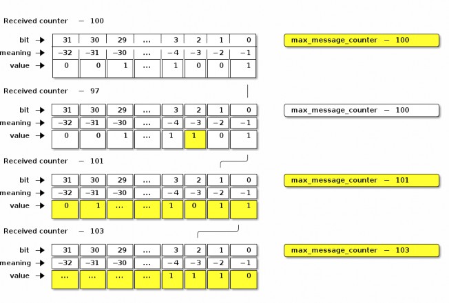
Figure 7. Message Reception State Example
Use of Message Reception State for Encrypted Messages
The algorithm for querying and updating message reception state varies slightly depending on whether the system is tracking reception of encrypted messages or unencrypted messages.
Message Counters with maximum
For encrypted messages of Secure Unicast Session Type, any arriving message with a counter in the range [(max_message_counter + 1) to (232 - 1)] SHALL be considered new, and cause the max_message_counter value to be updated. Message counters within the range of the bitmap SHALL be considered duplicate if the corresponding bit offset is set to true. All other message counters SHALL be considered duplicate.
Message Counters with rollover
A message counter with rollover is a free running message counter that monotonically increases, but rolls over to zero when it exceeds the maximum value of the counter (32-bits). Group keys are secured by a shared, global message counter with rollover as described in Section 4.5.1.3, “Global Group Encrypted Message Counters”.
For encrypted messages of Group Session Type, any arriving message with a counter in the range [(max_message_counter + 1) to (max_message_counter + 231 - 1)] (modulo 232) SHALL be considered new, and cause the max_message_counter value to be updated. Messages with counters from
[(max_message_counter - 231) to (max_message_counter - MSG_COUNTER_WINDOW_SIZE - 1)] (modulo 2
32) SHALL be considered duplicate. A message counter equal to max_message_counter SHALL be considered duplicate. Message counters within the range of the bitmap SHALL be considered duplicate if the corresponding bit offset is set to true.
This scheme for encrypted messages effectively divides the message counter space in half: those counters that are forward of the max message counter, which are considered new, and those counters that are behind the max message counter, which are considered duplicates unless indicated otherwise by the values in the bitmap.
Use of Message Reception State for Unencrypted Messages
For unencrypted messages, the algorithms for tracking messages and detecting duplicates are similar to, but more permissive than for encrypted messages using Section 4.5.4.2.2, “Message Counters with rollover”. This reflects the fact that duplicate detection of unencrypted messages is not done for security reasons, but rather to catch duplicates caused by network errors (e.g. loss of an ack), which are generally more bounded in time. The more relaxed algorithm for unencrypted duplicate detection also relaxes the durability requirement on the sender’s message counter, allowing senders to store the counter in RAM.
For unencrypted messages, any message counter equal to max_message_counter or within the message counter window, where the corresponding bit is set to true SHALL be considered duplicate. All other message counters, whether behind the window or ahead of max_message_counter, are considered new and shall update max_message_counter and shift the window accordingly. Messages with a counter behind the window are likely caused by a node rebooting and are thus processed as rolling back the window to the current location. Note that when max_message_counter is close to the minimum of the range, the window shall roll back to cover message counters near the maximum of the range.
Message Reception State Initialization
To initialize Message Reception State for a given Peer Node ID, initial max_message_counter, Message
Type (control or data), Encryption Level (encrypted or unencrypted), and Encryption Key (for any Encryption Level except unencrypted):
The Message Reception State fields SHALL be set as follows:
The Peer Node ID SHALL reference the given Peer Node ID.
The Message Type SHALL be the given Message Type.
The Encryption Level SHALL be the given Encryption Level.
If the Encryption Level is NOT unencrypted, the Encryption Key SHALL reference the given key.
The max_message_counter SHALL be set to the given max_message_counter.
The Message Counter bitmap SHALL be set to all 1, indicating that only new messages with counter greater than max_message_counter SHALL be accepted.
Counter Processing of Outgoing Messages
Obtain the outgoing message counter of the sending Node for the given Security Flags, Session Id, and Encryption Key:
A message of Unsecured Session Type SHALL use the current Global Unencrypted Message Counter.
A message of Secure Unicast Session Type SHALL use the current Secure Session Message Counter for the session associated with the Session ID.
A message of Group Session Type SHALL use:
The Global Group Encrypted Data Message Counter if the Security Flags C Flag = 0.
The Global Group Encrypted Control Message Counter if the Security Flags C Flag = 1.
The outgoing message counter from step 1 SHALL be incremented by 1.
Store the incremented outgoing message counter in the OutgoingMessageCounter element associated with the Session Context for the message.
If the message counter wraps around from 0xFFFF_FFFF to 0x0000_0000 and the message is of Secure Unicast Session Type:
The Encryption Key SHALL be expired in the Session Context. The session will need to be renegotiated to resume communication after transmission of this final message.
Counter Processing of Incoming Messages
Determine the Message Reception State for the sending peer and get the current
max_message_counter.
Given a decrypted message of Unicast Session Type:
Get the session-specific Message Reception State from the Secure Unicast Session Context.
Given a decrypted message of Group Session Type:
Extract the Source Node ID from the Message Header.
If there is no Source Node ID for the message, drop the message.
Get the Message Reception State for the Source Node ID of the given message:
If the Security Flags C Flag = 0, get the Data Message Reception State for the peer node.
If the Security Flags C Flag = 1, get the Control Message Reception State for the peer node.
If there is no Message Reception State for the groupcast message, initiate Section 4.16.4, “Unsynchronized Message Processing”.
Given an unencrypted message:
Get the Message Reception State associated with the Unsecured Session Context.
If there is no Message Reception State for the unencrypted message, create it with the information from the given message.
If the Message Counter is outside the valid message counter window, the message SHALL be marked as a duplicate. Note that while messages may be outside of the window for reasons other than being a duplicate, and we always mark them as such.
If the message is a duplicate:
If the message is marked as encrypted, follow Section 4.5.4.2, “Use of Message Reception State for Encrypted Messages”.
If the message is marked as unencrypted, follow Section 4.5.4.3, “Use of Message Reception State for Unencrypted Messages”.
If the message is encrypted and marked as a duplicate, i.e. Message Counter is outside the valid message counter window or marked as previously received in the Message Reception State:
Perform Section 4.11.5.2, “Reliable Message Processing of Incoming Messages” on the duplicate message.
Otherwise, update the Message Reception State as detailed in Section 4.5.4.1, “Message Reception State”, and accept the message for further processing.
Message Processing
This sub-clause describes the fundamental procedures for transmission and reception.
Message Transmission
To prepare a message for transmission with a given Session ID, Destination Node ID (which may be a group node id or an operational node id) and Security Flags, the following steps SHALL be performed, in order:
Process the message as described in Section 4.5.5, “Counter Processing of Outgoing Messages”.
If the message’s Session Type is a Unicast Session:
Set SessionTimestamp to a timestamp from a clock which would allow for the eventual determination of the last session use relative to other sessions.
Process the message as described in Section 4.7.2, “Security Processing of Outgoing Messages”.
Process the message as described in Section 4.8.2, “Privacy Processing of Outgoing Messages”.
Message Reception
To process a received message, the following steps SHALL be performed in order:
Perform validity checks on the message; if any fail, processing of the message SHALL stop, and a 'message invalid' error SHOULD be indicated to the next higher layer:
The Version field SHALL be 0.
If the message is of Secure Unicast Session Type:
The DSIZ field SHALL NOT indicate a Group ID is present.
If the message is of Group Session Type:
The DSIZ field SHALL NOT be 0.
The S Flag field SHALL NOT be 0.
If the message is NOT of Unsecured Session Type:
Obtain the Privacy and Encryption Keys associated with the given Session ID:
If no keys are found, security processing SHALL indicate a failure to the next higher layer with a status of 'message security failed' and no further security processing SHALL be done on this message.
For each Privacy and Encryption Key, of which there may be more than one in the case of group messages:
If the P Flag is set, follow Section 4.8.3, “Privacy Processing of Incoming Messages” to deobfuscate the message.
Follow Section 4.7.3, “Security Processing of Incoming Messages” to decrypt and authenticate the message.
Follow Section 4.5.6, “Counter Processing of Incoming Messages” to enforce replay protection and duplicate detection.
If the message transport is UDP, follow Section 4.11.5.2, “Reliable Message Processing of Incoming Messages” to process message reliability.
If the message’s Session Type is a Unicast Session:
Set SessionTimestamp and ActiveTimestamp to a timestamp from a clock which would allow for the eventual determination of the last session use relative to other sessions.
The received message is then delivered to Section 4.9.5, “Exchange Message Processing”.
Message Security
The detailed steps involved in security processing of outgoing and incoming Matter messages are described in Section 4.7.2, “Security Processing of Outgoing Messages” and Section 4.7.3, “Security
Processing of Incoming Messages” respectively. Section 4.7.1, “Data confidentiality and integrity with data origin authentication parameters” defines how the cryptographic parameters are set for securing Matter messages.
Data confidentiality and integrity with data origin authentication parameters
This section specifies the parameters to use the data confidentiality and integrity cryptographic primitive as defined in Section 3.6, “Data Confidentiality and Integrity”.
The parameters in this section SHALL apply for all encrypted messages, i.e. all messages except those of Unsecured Session Type.
Nonce
The nonce SHALL be formatted as specified in Table 16, “Nonce”.
Table 16. Nonce
Octets: 1
4
8
Security Flags
Message Counter
Source Node ID
The nonce used for the Authenticated Encryption with Additional Data (AEAD) algorithm (see Section 3.6, “Data Confidentiality and Integrity”) for a given message SHALL be defined as the concatenation of the Security Flags, the Message Counter, and the Source Node ID of that message. The scalar fields in the nonce, namely the Message Counter and the Source Node ID SHALL be encoded in little-endian byte order for the purposes of serialization within the nonce, that is, in the same byte ordering as the segment of the message from which its data originates.
The Source Node ID field used in the nonce SHALL be set to the Operational Node ID of the node originating security protection of the message:
If the message is of Secure Unicast Session Type:
For a CASE session, the Nonce Source Node ID SHALL be determined via the Secure Session Context associated with the Session Identifier.
For a PASE session, the Nonce Source Node ID SHALL be Unspecified Node ID.
If the message is of Group Session Type:
The S Flag of the message SHALL be 1 and the Nonce Source Node ID SHALL be the Source Node ID of the message.
If the S Flag of the message is 0 the message SHALL be dropped.

NOTE
Because PASE negotiates strong one-time keys per session and the I2RKey and R2IKey are distinct for each direction of communication, the use of the Unspecified Node ID as the Nonce Source Node ID remains semantically secure.
Security Processing of Outgoing Messages
The process for encrypting Matter messages is depicted graphically in Figure 8, “Matter Message Encryption” with color code conventions described in Figure 9, “Matter Message Encryption Legend”.
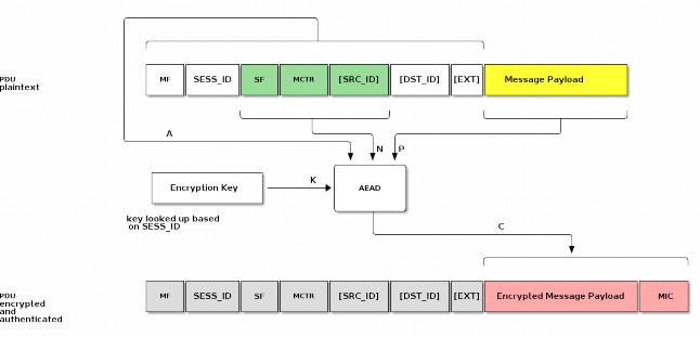
Figure 8. Matter Message Encryption
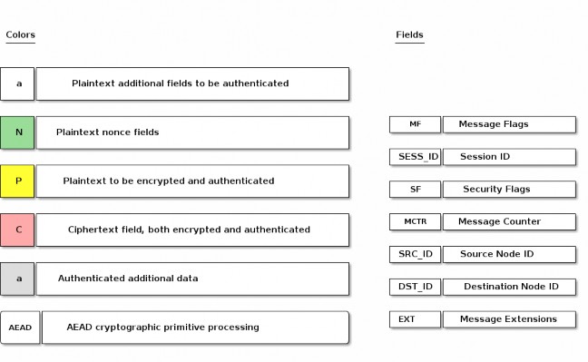
Figure 9. Matter Message Encryption Legend
To prepare a secure message for transmission with a given Session ID, Destination Node ID (which may be a group node id or an operational node id) and Security Flags, the Node SHALL perform the following steps:
Obtain the Encryption Key associated with the Session ID and Destination Node ID and the Session Type associated with the Destination Node ID:
If no key is found for the given Session ID, security processing SHALL fail and no further security processing SHALL be done on this message.
Obtain the outgoing message counter of the sending Node as per Section 4.5.5, “Counter Processing of Outgoing Messages”.
Set the Security fields as follows:
The Session ID field SHALL be set to the value provided to step 1.
The Security Flags field SHALL be set to the value provided to step 1 with the following subfields updated:
The Session Type field SHALL be set to the value obtained from step 1.
Set the Message Flags, Destination Node ID, and Source Node ID fields as follows:
If the Session Type is a unicast session:
Set S Flag to 0.
Set DSIZ to 0.
Omit both Destination Node ID, and Source Node ID.
Else if the Session Type is a group session:
Set S Flag to 1.
Set DSIZ to 2.
Set Source Node ID field to the operational node id of the sending node.
Set Destination Node ID field to the 16-bit Group ID derived from the Destination Node ID.
Set the Message Counter field to the outgoing message counter from step 2.
Execute the AEAD generate and encrypt operation, as specified in Section 3.6.1, “Generate and encrypt”, with the following instantiations:
The bit string key K SHALL be the Encryption Key obtained from step 1;
The nonce N SHALL be the CRYPTO_AEAD_NONCE_LENGTH_BYTES-octet string constructed according to Table 16, “Nonce”;
The parameter P SHALL be the Message Payload;

Message Flags || Session ID || Security Flags || Message Counter
The additional data octet string A SHALL be the Message Header contents, using little-endian byte order for all scalars, exactly as they appear in the message segments from which they originate:
with the optional fields appended according to the Message Flags:

[Source Node ID] || [Destination Node ID] || [Message Extensions]
C = Crypto_AEAD_GenerateEncrypt(K, P, A, N)
If the AEAD operation invoked in step 6 results in an error, then security processing SHALL fail and no further security processing SHALL be done on this message.

A || C
Let C be the output from step 6. C contains the tag of CRYPTO_AEAD_MIC_LENGTH_BITS bits (Message Integrity Check (MIC)) as specified by Section 3.6.1, “Generate and encrypt”. The secured outgoing message SHALL be:
Security Processing of Incoming Messages
All incoming message processing SHALL occur in a serialized manner. If an implementation chooses to process messages in a parallel manner, it must ensure that the behavior is opaque-box identical to a serialized processing implementation.
If the transport layer receives a secured message as indicated by the Session ID, it SHALL perform the following steps:
Determine the Session Type, Session ID, and Message Counter from the message header of the received message.
Obtain the Encryption Key associated with the Session Context of the given Session ID and Session Type:
If no key is found for the given Session ID, security processing SHALL indicate a failure to the next higher layer with a status of 'message security failed' and no further security processing SHALL be done on this message.
Execute the AEAD decryption and verification operation as specified in Section 3.6.2, “Decrypt and verify” with the following instantiations:
The bit string key K SHALL be the Encryption Key obtained from step 2;
The nonce N SHALL be the CRYPTO_AEAD_NONCE_LENGTH_BYTES-octet string constructed according to Table 16, “Nonce”;
The parameter C SHALL be the encrypted and authenticated Message Payload;
The additional data octet string A SHALL be the authenticated Message Header:
{success, P} = Crypto_AEAD_DecryptVerify(K, C, A, N)
Return the result {success, P} of the AEAD operation:
If the success is FALSE, security processing SHALL fail and further processing SHALL NOT be performed on this message. An appropriate error SHOULD be raised to the upper layer to indicate the error.
Otherwise, set the octet string PlaintextMessage to the string

A || P
PlaintextMessage now represents the deciphered, authenticated, received message.
NOTE: The message has not yet undergone counter processing nor replay detection.
The PlaintextMessage SHALL be marked as successfully security processed and SHALL be released to the next processing layer.
Message Privacy
Privacy processing of a message describes the obfuscation and deobfuscation of the message header fields after encryption and before decryption.
The detailed steps involved in privacy processing of outgoing and incoming Matter messages are described in Section 4.8.2, “Privacy Processing of Outgoing Messages” and Section 4.8.3, “Privacy Processing of Incoming Messages” respectively. They rely on the cryptographic primitives in Section 3.7, “Message privacy”.
Privacy Key

PrivacyKey =
Crypto_KDF (
InputKey = EncryptionKey, Salt = [],
Info = "PrivacyKey",
Length = CRYPTO_SYMMETRIC_KEY_LENGTH_BITS
)
The Privacy Key is a symmetric key specifically used for Privacy Processing that is derived from the EncryptionKey used for Security Processing of a given message. Given a Session ID reference to a specific Encryption Key, the Privacy Key is derived as follows:
Privacy Processing of Outgoing Messages
The process for privacy encoding Matter message headers is depicted graphically in Figure 10, “Matter Message Privacy”.
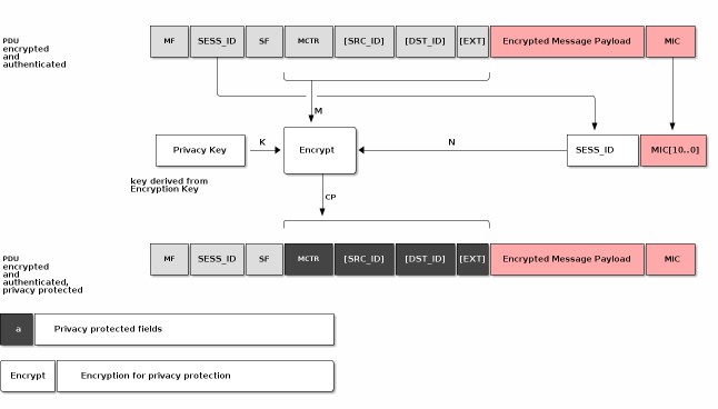
Figure 10. Matter Message Privacy
To apply privacy obfuscation to an encrypted message prepared for transmission by Section 4.6.1, “Message Transmission”, apply obfuscation steps as follows:
If P Flag is not set, do nothing.
Obtain the Privacy Key for the Encryption Key used to secure the message.
Execute the encryption operation as specified in Section 3.7.1, “Privacy encryption” with the following instantiations:
The bit string key K SHALL be the Privacy Key obtained from step 1;
The MIC SHALL be the last CRYPTO_AEAD_MIC_LENGTH_BYTES bytes of the C outcome of the message security protection as specified in Section 4.7.2, “Security Processing of Outgoing Messages” (MIC = C[(CRYPTO_AEAD_MIC_LENGTH_BYTES-1)..0])

N = Session ID || MIC[(CRYPTO_AEAD_NONCE_LENGTH_BYTES-3)..0]
The nonce N SHALL be the CRYPTO_AEAD_NONCE_LENGTH_BYTES-octet string constructed as the 16-bit Session ID (in big-endian format) concatenated with the lower (CRYPTO_AEAD_NONCE_LENGTH_BYTES-2) bytes of the MIC:

Session ID = 00:2A
MIC = c5:a0:06:3a:d5:d2:51:81:91:40:0d:d6:8c:5c:16:3b N = 00:2A:d2:51:81:91:40:0d:d6:8c:5c:16:3b
For example if Session ID = 42 (i.e. 0x002A) and the computed MIC is 0xc5a0063ad5d2518191400dd68c5c163b:
The parameter M SHALL be the message header fields where optional fields are only

M = Message Counter || [Source ID] || [Destination ID] || [Message Extensions]
present in M if they are present in the message:
CP = Crypto_Privacy_Encrypt(K, M, N)
Let CP be the obfuscated output from step 2. CP SHALL be used in the final private message in place of the message header fields.
Privacy Processing of Incoming Messages
To deobfuscate a private message received by Section 4.6.2, “Message Reception” with a given Privacy Key, perform security processing as follows:
If P Flag is not set, do nothing.
With the given Privacy Key, execute the decryption as specified in Section 3.7.2, “Privacy decryption” with the following instantiations:
The bit string key K SHALL be the Privacy Key obtained from step 1;
The MIC SHALL be the last CRYPTO_AEAD_MIC_LENGTH_BYTES bytes of the C outcome of the message security protection as specified in Section 4.7.3, “Security Processing of Incoming Messages” (MIC = C[(CRYPTO_AEAD_MIC_LENGTH_BYTES-1)..0])

N = Session ID || MIC[(CRYPTO_AEAD_NONCE_LENGTH_BYTES-3)..0]
The nonce N SHALL be CRYPTO_AEAD_NONCE_LENGTH_BYTES-octet string constructed as the 16-bit Session ID (in big-endian format) concatenated with the lower (CRYPTO_AEAD_NONCE_LENGTH_BYTES-2) bytes of the MIC:

CP = Message Counter || [Source ID] || [Destination ID] || [Message Extensions]
The parameter CP SHALL be the message header fields where optional fields are only present in CP if they are present in the message:
M = Crypto_Privacy_Decrypt(K, CP, N)
Let M be the deobfuscated output from step 2.
M SHALL be used in the final private message in place of the message header fields.
The first successfully validated message, M, by Section 4.7.3, “Security Processing of Incoming Messages” SHALL terminate iteration through Privacy Keys in step 2.
Message Exchanges
An Exchange provides a way to group related messages together, organize communication flows, and enable higher levels of the communication stack to track semantically relevant groupings of messages.
An Exchange SHALL be bound to exactly one underlying session that will transport all associated Exchange messages for the life of that Exchange. The underlying session SHALL be one of the following session types: secure unicast (as established by PASE or CASE), unsecured (as is used for the initial session establishment phase of a PASE/CASE session), secure group, or MCSP.
When used with reliability, Exchanges assume basic flow control by the upper layer. The Exchange Layer SHALL not accept a message from the upper layer when there is an outbound reliable message pending on the same Exchange.
Exchange Role
The first Node to send a message in an Exchange is said to be in the Initiator role, and all the other Nodes that subsequently participate in the Exchange are said to be in a Responder role. An Exchange is always between one Initiator and one or more peer Responder Nodes. An Exchange does not survive a reboot of one of the participants. Adjacent layers MAY close an Exchange at any time.
Exchange ID
An Exchange of messages is identified by the Exchange ID field described in Section 4.4.3.3, “Exchange ID (16 bits)”. The Exchange ID is allocated by the Initiator. The first message the Initiator sends in a new Exchange SHALL contain a fresh value for the Exchange ID field. The Exchange is then identified by the tuple {Session Context, Exchange ID, Exchange Role} where Session Context is one of an Unsecured, Secured, Groupcast or MCSP session context. All messages that are part of a given Exchange, whether they are sent by the Initiator or not, share the same Exchange ID, allowing the Initiator and Responder Nodes to match responses to requests or otherwise group messages together that are part of more complex transactions. The first Exchange ID for a given Initiator Node SHALL be a random integer. All subsequent Exchange IDs created by that Initiator SHALL be the last Exchange ID it created incremented by one. An Exchange ID is an unsigned integer that rolls over to zero when its maximum value is exceeded.
Exchange Context
An Exchange context is the metadata tracked for an Exchange by all exchange participants. An Exchange context tracks the following data:
Exchange ID: The Exchange ID assigned by the Initiator
Exchange Role: Initiator or Responder
Session Context: The underlying Unsecured, Secured, Groupcast or MCSP session context
Together, Session Context, Exchange ID and Role comprise a unique key allowing participants to identify any exchange.
4.9.3.1. Protocol ID Registration
The Interaction Model layer indicates to the Exchange Layer which Protocols it will accept. Any message for a Protocol ID that is not registered with the Exchange Layer SHALL be dropped.
Exchange Message Dispatch
When sending a message to the Exchange Layer, the next higher layer SHALL specify whether the message is part of an existing Exchange, or the first of a new Exchange. For the case of a first message, the Initiator creates a new Exchange. The Node in the Initiator role SHALL always set the I Flag in the Exchange Flags of every message it sends in that Exchange.
Each Node in a Responder role for an Exchange SHALL use the Exchange ID received in previous messages for the Exchange. Each Node in the Responder role SHALL NOT set the I Flag in the Exchange Flags of every message it sends in that Exchange. Each Node in a Responder role SHALL NOT set the Destination Node ID field to a value that identifies any Node other than the Node in the Initiator role for the Exchange.
Processing SHALL then proceed to Section 4.11.5.1, “Reliable Message Processing of Outgoing Messages”.
Exchange Message Processing
After completion of Section 4.6.2, “Message Reception”, if the message matches an existing Exchange, it is dispatched to the appropriate protocol handler in the next higher layer. Messages for an existing Exchange are dispatched to the handler for that Exchange. Otherwise, the unsolicited message that created the Exchange is dispatched to the unsolicited message handler.
Exchange Message Matching
Upon receipt of a message, the Exchange Layer attempts to match the message to an existing Exchange. A given message is part of an Exchange if it satisfies all the following criteria:
The message was received over the session associated with the Exchange.
The Exchange ID of the message matches the Exchange ID of the Exchange,
The message has the I Flag set and the Exchange Role of the Exchange is Responder,
OR the message does not have the I Flag set and the Exchange Role of the Exchange is Initiator.
If the message does not match an existing Exchange, the message is considered an unsolicited message.
Unsolicited Message Processing
An unsolicited message is processed as follows:
If the unsolicited message is not marked as having a duplicate message counter, has a registered Protocol ID, and the I Flag is set:
Create a new exchange from the incoming message.
The new exchange will be used by the upper layer for generating responses and subsequent processing of the message.
Otherwise, if the message has the R Flag set:
Create an ephemeral exchange from the incoming message and send an immediate
standalone acknowledgement.
The message SHALL NOT be forwarded to the upper layer, and excluding the sending of an immediate standalone acknowledgment, SHALL be ignored.
The ephemeral exchange created for such duplicate or unknown messages with R Flag set is automatically closed in Section 4.11.5.2.2, “Standalone acknowledgement processing”.
Otherwise, processing of the message SHALL stop.
Creating an Exchange based on an Incoming Message
The steps to create a new Exchange based on an incoming message are as follows:
A new Exchange and Exchange Context SHALL be created with the following settings:
The Exchange ID SHALL be set to the Exchange ID of the message.
The Exchange Role SHALL be set to the inverse of the incoming message I Flag, for example set the Exchange Role to Responder if the message is from an Initiator.
The Session Context SHALL be set to the Session on which the message was received.
Closing an Exchange
An Exchange MAY be closed by the application layer or a fatal connection error from the lower message layer. The process of closing an Exchange follows:
Any pending acknowledgements associated with the Exchange SHALL be flushed. If there is a pending acknowledgment in the acknowledgement table for the Exchange and it has StandaloneAckSent set to false:
Immediately send a standalone acknowledgement for the pending acknowledgement.
Remove the acknowledgement table entry for the pending acknowledgement.
Wait for all pending retransmissions associated with the Exchange to complete.
If the retransmission list for the Exchange is empty, remove the Exchange.
Otherwise, leave the Exchange open and only close it once the retransmission list is empty.
These steps are depicted in Figure 11, “Exchange close flow”.
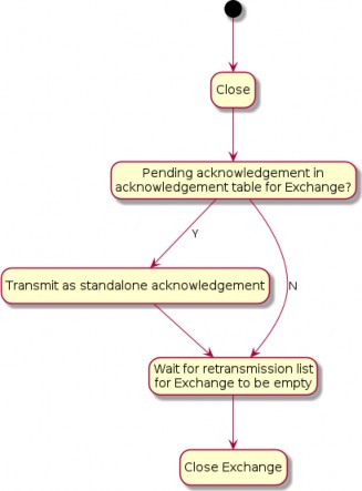
Figure 11. Exchange close flow
Secure Channel Protocol
This section specifies the formal protocol definition for the Secure Channel Protocol. Secure Channel Protocol defines the control plane for secure channel communication and security.
Secure Channel Protocol Messages
Secure Channel Protocol is composed of a collection of sub-protocols, including:
Message Counter Synchronization Protocol (MCSP)
Message Reliability Protocol (MRP)
Passcode Based Session Establishment (PASE)
Certificate Based Session Establishment (CASE)
The protocol opcodes for messages within the Secure Channel Protocol are grouped based on the underlying sub-protocol that uses the message type. Table 17, “Secure Channel Protocol Opcodes” lists the messages defined by Secure Channel Protocol.
Table 17. Secure Channel Protocol Opcodes
Protocol Opcode
Protocol Command Name
Description
Protocol ID = PROTOCOL_ID_SECURE_CHANNEL
Protocol Opcode
Protocol Command Name
Description
0x00
MsgCounterSyncReq
The Message Counter Synchronization Request message queries the current message counter from a peer to bootstrap replay protection.
0x01
MsgCounterSyncRsp
The Message Counter Synchronization Response message provides the current message counter from a peer to bootstrap replay protection.
0x10
MRP Standalone Acknowledgement
This message is dedicated for the purpose of sending a stand-alone acknowledgement when there is no other data message available to piggyback an acknowledgement on top of.
0x20
PBKDFParamRequest
The request for PBKDF parameters necessary to complete the PASE protocol.
0x21
PBKDFParamResponse
The PBKDF parameters sent in response to PBKDFParamRequest during the PASE protocol.
0x22
PASE Pake1
The first PAKE message of the PASE protocol.
0x23
PASE Pake2
The second PAKE message of the PASE protocol.
0x24
PASE Pake3
The third PAKE message of the PASE protocol.
0x30
CASE Sigma1
The first message of the CASE protocol.
0x31
CASE Sigma2
The second message of the CASE protocol.
0x32
CASE Sigma3
The third message of the CASE protocol.
0x33
CASE Sigma2_Resume
The second resumption message of the CASE protocol.
0x40
StatusReport
The Status Report message encodes the result of an operation in the Secure Channel as well as other protocols.
Session Establishment - Out of Resources
After a successful session establishment using CASE or PASE, a responder may not have enough resources to save all of the session context information. To free resources, a responder SHALL evict an existing session using the following procedure:
Use the SessionTimestamp to determine the least-recently used session.
Determine the session that was least-recently used then:
Send a status report: StatusReport(GeneralCode: SUCCESS, ProtocolId: SECURE_CHANNEL,
ProtocolCode: CLOSE_SESSION) message to the peer node
Remove all state associated with the session (see Section 4.12.2.1, “Secure Session Context”). The Node MAY save state necessary to perform Session Resumption, see Section 4.13.2.2.1, “Session Resumption State” for more details.
Respond to the initiator with the appropriate session establishment message
Status Report
The Status Report message is sent from protocol handlers to convey the status of an operation using a common format as defined in Appendix D, Status Report Messages. The StatusReport message is a part of the Secure Channel protocol, but embeds an additional context-specific ProtocolID field in its message-specific payload. In this way, the StatusReport can convey status for any protocol handler.
Secure Channel Status Report Messages
Status Reports specific to the Secure Channel are designated by embedding the PROTOCOL_ID_SECURE_CHANNEL in the ProtocolId field of the StatusReport body. All Secure Channel Status Report Messages SHALL use the PROTOCOL_ID_SECURE_CHANNEL protocol id. For example, a failure to find a common root of trust may be written in the specification as follows:
StatusReport(GeneralCode: FAILURE, ProtocolId: SECURE_CHANNEL, ProtocolCode:
NO_SHARED_TRUST_ROOTS).
There are several cases for which the secure channel layer may emit a status report:
To indicate successful session establishment
In response to errors during session establishment
In response to errors after session establishment
To indicate that a Node is terminating a session
For each of these cases, a Secure Channel Status Report message SHALL be sent with an appropriate
ProtocolCode as detailed below.
The following table describes the Secure Channel Status Report Protocol Specific codes. Each entry in the list details the appropriate General Code to be utilized with the message and whether it may be sent unencrypted. Secure Channel Status Report messages which are marked as encrypted below SHALL only be sent encrypted in a session established with CASE or PASE.
Table 18. Secure Channel Protocol Codes
Protocol Code
Error
General Code
Encrypted
Additional Data
Description
0x0000
SESSION_ESTABLISHM ENT_SUCCESS
SUCCESS
N
N
Indication that the last session establishment message was successfully processed.
0x0001
NO_SHARED_TRUST_RO OTS
FAILURE
N
N
Failure to find a common set of shared roots.
0x0002
INVALID_PARAMETER
FAILURE
N
N
Generic failure during session establishment.
0x0003
CLOSE_SESSION
SUCCESS
Y
N
Indication that the sender will close the current session. See Section 4.10.1.4, “CloseSession” for more details.
Protocol Code
Error
General Code
Encrypted
Additional Data
Description
0x0004
BUSY
BUSY
N
Y
Indication that the sender cannot currently fulfill the request. See Section 4.10.1.5, “Busy” for more details.
CloseSession
A node may choose to close a session for a variety of reasons including, but not limited to, the following:
The interaction between nodes is complete
The node needs to free up resources for a new session
Fabric configuration associated with the CASE session was removed with the RemoveFabric command invoked by an Administrator while the session was open
The CloseSession StatusReport SHALL only be sent encrypted within an exchange associated with a PASE or CASE session. The CloseSession StatusReport SHALL be sent within a new exchange and SHALL NOT set the R Flag.
If a Node has either sent or received a CloseSession StatusReport, that Node SHALL remove all state associated with the session (see Section 4.12.2.1, “Secure Session Context”). The Node MAY save state necessary to perform Session Resumption, see Section 4.13.2.2.1, “Session Resumption State” for more details.
Busy
When a receiver receives a request to start a new secure session via a Sigma1 or PBKDFParamRequest message, the receiver MAY respond with the BUSY StatusReport when it is unable to fulfill the request. The BUSY StatusReport SHALL:
Set the R Flag to 0
Set the S Flag to 0
Set the StatusReport ProtocolData to a 16-bit (two byte) little-endian value indicating the minimum time in milliseconds to wait before retrying the original request.
Set the Exchange ID to the Exchange ID present in the Sigma1 or PBKDFParamRequest message which triggered this response.
For example, a responder wishing to indicate they are unable to fulfill the request and that the initiator should wait 500 milliseconds before trying again would send StatusReport(GeneralCode: BUSY, ProtocolId: SECURE_CHANNEL, ProtocolCode: BUSY, ProtocolData: [0xF4, 0x01]).
The BUSY StatusReport SHALL NOT be sent in response to any message except for Sigma1 or PBKDFParamRequest.
An initiator receiving a BUSY StatusReport from a responder SHALL wait for at least a period of t
milliseconds before retrying the request where t is the value obtained from the Busy StatusReport
ProtocolData field.
If the initiator sends a new session establishment request after receiving a BUSY StatusReport, the request SHALL contain new values for all randomized parameters.
Parameters and Constants
Table 19, “Glossary of constants” is a glossary of constants used in the secure channel protocol, along with a brief description and the default for each constant.
Table 19. Glossary of constants
Constant Name
Description
Value
MSG_COUNTER_WINDOW_SIZE
Maximum number of previously processed message counters to accept from a given Node and key.
32
MSG_COUNTER_SYNC_REQ_JITTE R
Maximum amount of random delay before sending a MsgCounterSyncReq when the synchronization request is triggered by receipt of a multicast message.
500
milliseconds
MSG_COUNTER_SYNC_TIMEOUT
The maximum amount of time (in milliseconds) which a Node SHALL wait for a MsgCounterSyncRsp after sending a MsgCounterSyncReq.
400
milliseconds
Message Reliability Protocol (MRP)
The Message Reliability Protocol (MRP) provides confirmation of delivery for messages that require reliability. The protocol is optimized for constrained devices that may not be able to receive a message at the point it is due to be delivered to them. Reliable messaging MAY be enabled on an individual message basis as required by the protocol design of the higher layer application. Reliability is achieved through time-bounded delivery confirmation, ensuring best effort delivery of critical messages over what may be an inherently lossy and unreliable communication medium.
Flow control mechanisms are not incorporated in MRP because it is intended to be used for short interactions with small numbers of messages in them.
Reliable Messaging Header Fields
The following fields are defined in the Exchange Flags for use exclusively by MRP:
R Flag
Indicates a reliable message. This flag SHALL be set by the sender when a message being sent requires the receiver to send back an acknowledgment. To support unreliable messages, this flag bit MAY be clear, so that no acknowledgements are requested from the receiver.
A Flag
Indicates the message is acting as an acknowledgement. This flag MAY be set on any message. When set, the Acknowledged Message Counter field SHALL be present and valid. This flag SHALL always be set for MRP Standalone Acknowledgement messages.
Acknowledged Message Counter
This field SHALL be set to the Message Counter of the message that is being acknowledged.
Reliable transfer
When the reliability bit is set, the reliable message is transmitted at most MRP_MAX_TRANSMISSIONS times until an acknowledgement of receipt is received from the peer or a timeout.
Retransmissions
Senders provide an automatic retransmission mechanism for reliable messages. In order for the receiver to receive a message reliably, the sender SHALL trigger the automatic retry mechanism after a period of backoff_time milliseconds without receiving an acknowledgement, where backoff_time set to t as calculated in the formula below. The sender SHALL retry up to a configured maximum number of times (MRP_MAX_TRANSMISSIONS - 1) before giving up and notifying the application.
Messages sent to a Node can be lost for various reasons such as lossy network or insufficient buffer space at the receiver. In the case of sleepy end devices, which wake up infrequently to receive messages destined for them, a sender must be aware of the characteristics of the recipient to ensure it does not attempt to send at a rate beyond the recipient’s capability. Therefore, the sender SHALL choose retransmission timeouts based on the sleepy characteristics of the destination Node using Section 4.3.2, “Operational Discovery”.

t = i * "MRP_BACKOFF_BASE"^(max(0,n-"MRP_BACKOFF_THRESHOLD")) * (1.0 + "random"(0,1) * "MRP_BACKOFF_JITTER")
At each sender, a retransmission timer is started each time a reliable message is transmitted. The duration of the retransmission timer SHALL be calculated as follows:

{:(t, =, "the resultant retransmission timeout for this transmission"),(n, =, "the number of send attempts before the current one for this message (0 if this is the initial transmission)"),(i, =, "the base retry interval for the Exchange (either IDLE or ACTIVE)"):}
Where:
For each unique Exchange, the sender SHALL wait for the acknowledgement message until the retransmission timer, t, expires.
The base interval, i, SHALL be set according to the active state of the peer node as stored in the Session Context of the session (either the Secure Session Context or the Unsecured Session Context depending on the Session Type). The backoff base interval SHALL be set to a value at least 10% greater than the sleep interval of the destination:
If PeerActiveMode in the Session Context is true:
i = SLEEPY_ACTIVE_INTERVAL of the peer
Else the peer is in idle mode:
i = SLEEPY_IDLE_INTERVAL of the peer
i = 1.1 * i
The MRP_BACKOFF_THRESHOLD parameter creates a two-phase scheme which begins with linear backoff to improve initial latency when congestion is not the cause of packet drops, and then transitions to exponential backoff to provide convergence when the network is congested. If a positive acknowledgment is received before the retransmission timer expires, the retransmission timer is stopped. Otherwise, if the retransmission timer expires, the message is retransmitted and the timer started again.
The following table illustrates minimum, maximum, and cumulative retransmission times using default parameters.
Table 20. Example MRP Retransmission Times
Metric
Transmission Time [ms]
Min Jitter
300
300
480
768
1228
Max Jitter
375
375
600
960
1536
Min Total
300
600
1080
1848
3076
Max Total
375
750
1350
2310
3846
Transmission #
0
1
2
3
4
The sender SHOULD initiate Section 4.3.2, “Operational Discovery” in parallel with the first retry to re-resolve the address of the destination Node if the initial transmission fails after one expected round trip. The sender SHOULD use the latest MRP parameters for the destination that result from subsequent Operational Discovery.
Acknowledgements
A receiver SHALL acknowledge a reliable message by either using a "piggybacked" acknowledgment in the next message destined to the peer, or a standalone acknowledgment, or both.
The acknowledgement message SHALL set the Acknowledged Message Counter field to the value of the Message Counter of the reliable message to be acknowledged.
Piggybacking Acknowledgments on Responses
Acknowledgements MAY be conveyed at the same time (i.e. piggybacked) as data in a response
message. The receiver tries to optimize message transmission by deferring acknowledgments when a reliable message is received (see Section 4.11.5.2.2, “Standalone acknowledgement processing”) and piggybacking outstanding acknowledgments on messages that it needs to send back (see Section 4.11.5.1.1, “Piggyback acknowledgment processing” for more details).
Duplicate Message Detection
Since the reliable messaging protocol has a provision for the sender to retransmit messages, there is a significant chance that a duplicate message may arrive at the receiver. The receiver SHALL detect and mark duplicate messages that it receives using the standard authentication and replay protection mechanisms of the secure message layer (see Section 4.5.4, “Replay Prevention and Duplicate Message Detection”). The receiver SHALL send an acknowledgment message to the sender for each instance of an authenticated, reliable message, including duplicates. The reliability layer SHALL only propagate the first instance of a message to the next higher layer. Any message marked as a duplicate SHALL be dropped by the reliability layer.
Peer Exchange Management
The Reliable Messaging Protocol operates within the scope of an Exchange between two Nodes. MRP SHALL support one pending acknowledgement and one pending retransmission per Exchange.
MRP control parameters are negotiated outside of the Exchange communication itself, and are determined during Operational Discovery. These parameters are detailed in Table 21, “Glossary of parameters”.
Transport Considerations
When the upper layer requests a reliable message over a UDP transport, the R Flag SHALL be set on that message indicating that MRP SHALL be used. Reliable messages sent over TCP or BTP SHALL utilize the underlying reliability mechanisms of those transports and SHOULD NOT set the R Flag.
Reliable Message Processing
Reliable Message Processing of Outgoing Messages
To prepare a given Protocol Message for transmission, the message SHALL be processed as follows:
Proceed to Section 4.11.5.1.1, “Piggyback acknowledgment processing”.
Piggyback acknowledgment processing
Determine if there is a matching pending acknowledgement in the acknowledgement table for the given message by checking all of the following conditions:
If the Destination Node Id and Exchange Id of the given message and pending acknowledgement are the same
AND either
the Session Id and underlying Session Credentials of the given message and pending
acknowledgement are the same
OR both the given message and pending acknowledgement are of Unsecured Session Type.
If there is a matching pending acknowledgement, the A Flag SHALL be set on the outbound message so it will serve as a piggybacked acknowledgement.
For such a piggybacked acknowledgement, the Acknowledgment Message Counter field SHALL be set to the message counter of the received message for which an acknowledgement was pending.
If the message being prepared is not a standalone acknowledgement, remove the matching entry from the acknowledgement table.
If the message being prepared is a standalone acknowledgement, set the StandaloneAckSent
field of the matching entry in the acknowledgement table to true.
Message retransmission processing
If the outbound message is marked to be delivered reliably over a UDP transport, the R Flag SHALL be set on the given message to request an acknowledgement from the peer upon receipt.
Any message flagged for reliable delivery (R Flag set) SHALL be stored in the retransmission table to track the message until it has been successfully acknowledged by the peer.
Perform Section 4.6.1, “Message Transmission” processing step on the message to send the message to the peer:
The same Session ID, Destination Node ID, Security Flags, and transport as were used for the initial message transmission SHALL be used.
If the transport interface returns an error on the send attempt, the error is assessed to determine whether the message can be retried.
If the error is fatal, the application is notified and the message removed from the
retransmission table.
If there is no error, or a non-fatal error such as no memory, the message is resent
Update the retransmission table to reflect the send count.
Start a retransmission timer to track the maximum time to wait before attempting another retransmission.
For each retry, the retransmission table is updated to track the number of retries until the maximum number is attempted, at which point the message is evicted from the retransmission table.
Send flow state diagram
The MRP send flow described above is depicted in the control flow diagram Figure 12, “MRP send flow”.
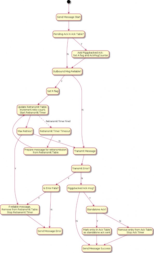
Figure 12. MRP send flow
Reliable Message Processing of Incoming Messages
A message received from Section 4.6.2, “Message Reception” for reliability processing SHALL be processed as follows:
Verify the message has a legal combination of reliability flags:
If the R Flag is set:
If Group Session Type AND C Flag = 0, drop the message.
If the A Flag is set:
If Group Session Type AND C Flag = 0, drop the message.
Proceed to Section 4.9.5.1, “Exchange Message Matching”.
Proceed to Section 4.11.5.2.1, “Received acknowledgement processing”.
Received acknowledgement processing
If the A Flag is set:
Query the retransmission table for the Acknowledgement Message Counter contained in the received message.
If there is a match:
Remove the entry from the retransmission table.
Stop the retransmission timer for that entry.
If there is no match, it indicates that this is either a duplicate acknowledgment or the Exchange context does not exist.
Proceed to Section 4.11.5.2.2, “Standalone acknowledgement processing”.
Standalone acknowledgement processing
If the R Flag is set, the received message is requesting an acknowledgement be sent back:
If the message is marked as a duplicate:
Immediately send a standalone acknowledgment.
If the Exchange is marked as an ephemeral exchange the Exchange SHALL be closed.
Drop the message.
Otherwise, instead of sending an acknowledgement immediately upon the receipt of a reliable message from a peer, the receiver SHOULD wait for a time no longer than MRP_STANDALONE_ACK_TIMEOUT before sending a standalone acknowledgment:
Add the message counter of the received message to the acknowledgement table to signal that an outbound acknowledgement is pending. There can be only one outstanding acknowledgement at a time on a single Exchange. If a pending acknowledgement already exists for the Exchange, and it has StandaloneAckSent set to false, a standalone acknowledgment SHALL be sent immediately for that pending message counter, and the acknowledgement table entry SHALL be replaced for the new message.
Start the acknowledgement timer for the Exchange.
If the timer triggers before being cancelled, a standalone acknowledgment SHALL be sent to the source of the message. Sending this standalone acknowledgment SHALL NOT remove the acknowledgement table entry and SHALL set the StandaloneAckSent field of the entry to true.
The received message is then delivered to the next processing step of Section 4.6.2, “Message Reception”.
Receive flow state diagram
The MRP receive flow described above is depicted in Figure Figure 13, “MRP receive flow”.
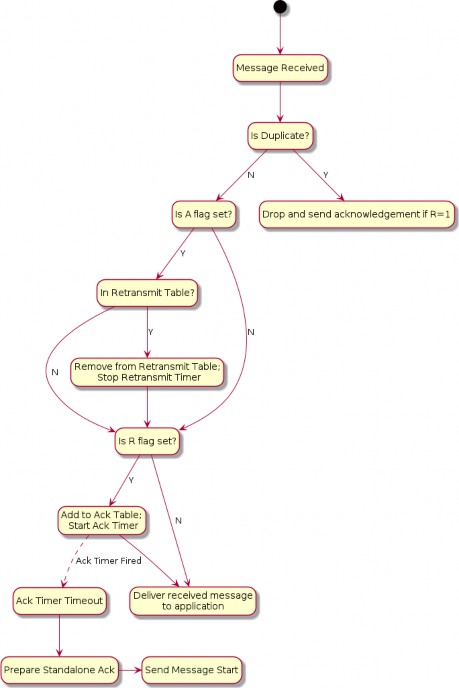
Figure 13. MRP receive flow
Reliable Message State
Retransmission Table
For retransmissions, the sender maintains a retransmission table of context records containing information on all reliable messages sent that have acknowledgments still pending. Each such reliable message context record includes the following fields:
Reference to Exchange Context
Message Counter
Reference to fully formed, encoded and encrypted message buffer
Send count
Retransmission timeout counter
Each time a message that requires acknowledgment is sent, a new retransmission context record is inserted into the retransmission table or an existing record is updated to increment its send count. The message is sent a configurable maximum number of times (MRP_MAX_TRANSMISSIONS) and, if still undelivered, the application is notified of the failure.
Acknowledgement Table
The receiver maintains an acknowledgement table of context records containing information on each reliable message for which an acknowledgment SHALL be sent. Each such reliable message context record includes the following fields:
Reference to Exchange Context
Message Counter
A boolean, StandaloneAckSent, indicating whether a standalone acknowledgement has been sent for this message counter. Initially false.
An entry SHALL remain in the table until one of the following things happens:
The exchange associated with the entry is closed. See Section 4.9.5.3, “Closing an Exchange”.
The exchange associated with the entry has switched to track a pending acknowledgement for a new message counter value. See Section 4.11.5.2.2, “Standalone acknowledgement processing”.
A message that is not a standalone acknowledgement is sent which serves as an acknowledgement for the entry. See Section 4.11.5.1.1, “Piggyback acknowledgment processing”.
MRP Messages
MRP Standalone Acknowledgement
The MRP Standalone Acknowledgement message SHALL be formed as follows:
The application payload SHALL be empty.
The A Flag SHALL be set to 1.
The Acknowledged Message Counter SHALL be included in the header.
The Protocol ID SHALL be set to PROTOCOL_ID_SECURE_CHANNEL.
The Protocol Opcode SHALL be set to MRP Standalone Acknowledgement.
The rules for when to send this message are detailed in Section 4.11.5.2.2, “Standalone acknowledgement processing”.
Parameters and Constants
Table 21, “Glossary of parameters” is a glossary of parameters used in this chapter with a brief description for each parameter. A Node SHALL use the provided default value for each parameter unless the message recipient Node advertises an alternate value for the parameter via Operational Discovery.
Table 21. Glossary of parameters
Parameter Name
Description
Default Value
MRP_MAX_TRANSMISSIONS
The maximum number of transmission attempts for a given reliable message. The sender MAY chose this value as it sees fit.
4
MRP_BACKOFF_BASE
The base number for the exponential backoff equation.
1.6
MRP_BACKOFF_JITTER
The scaler for random jitter in the backoff equation.
0.25
MRP_BACKOFF_THRESHOLD
The number of retransmissions before transitioning from linear to exponential backoff.
1
MRP_STANDALONE_ACK_TIMEOUT
Amount of time to wait for an opportunity to piggyback an acknowledgement on an outbound message before falling back to sending a standalone acknowledgement.
200
milliseconds
Unicast Communication
This section specifies the semantics of establishing a unicast session and the lifecycle of a unicast session.
Unicast sessions exist in one of two phases:
Session Establishment Phase: A series of well-defined unencrypted messages that aim to establish a shared key.
Application Data Phase: A series of ad-hoc encrypted messages exchanging interaction model protocol actions, application data, etc.
Session Establishment Phase
Session establishment uses either the CASE or PASE protocol.
CASE SHALL be used as a session establishment mechanism for all sessions except:
1. Communication for the purpose of commissioning when NOC has not yet been installed
PASE SHALL only be used for session establishment mechanism during device commissioning. PASE SHALL NOT be used as a session establishment mechanism for any other session. BTP MAY be used as the transport for device commissioning. BTP SHALL NOT be used as a transport for operational purposes.
Unless otherwise specified, the CASE, PASE, User-Directed Commissioning protocol, and Secure Channel Status Report messages SHALL be the only allowed unencrypted messages.
This phase aims to:
Authenticate peers (CASE-based sessions only).
Derive shared secrets to encrypt subsequent session data.
Choose session identifiers to identify the subsequent session.
Unsecured Session Context
The following session context data SHALL be utilized to associate messages to a particular peer and recover context during unencrypted sessions:
Session Role: Records whether the node is the session initiator or responder.
Ephemeral Initiator Node ID: Randomly selected for each session by the initiator from the Operational Node ID range and enclosed by initiator as Source Node ID and responder as Destination Node ID.
Initiators SHALL select a new random ephemeral node ID for each unsecured session, and SHALL select an ID that does not conflict with any ephemeral node IDs for any other ongoing unsecured sessions opened by the initiator.
Message Reception State: Provides tracking for the Unencrypted Message Counter of the remote peer.
Matching and responder creation of Unsecured Session Contexts SHALL be as follows:
Given an incoming unencrypted message
Locate any Unsecured Session Context with matching Ephemeral Initiator Node ID
If any is located, the incoming message SHALL be assumed to be associated with this
Unsecured Session Context
Else if the message carries a Source Node ID
Create a new Unsecured Session Context
Set Session Role to responder
Record the incoming message’s Source Node ID as Ephemeral Initiator Node ID
Else discard the message
Initiator creation of Unsecured Session Contexts SHALL be as follows:
Given the first outgoing message of an unencrypted exchange
Create a new Unsecured Session Context
Set Session Role to initiator
Randomly select a node ID from the Operational Node ID range that does not collide with any ephemeral node IDs for any other ongoing unsecured sessions opened by the initiator and record this as Ephemeral Initiator Node ID
Session Establishment over IP
When establishing a session over IP, the initiator SHALL use TCP when both of the following are true:
The initiator supports TCP
The responder supports TCP as indicated by the T flag
If one or both nodes do not support TCP, the initiator SHALL use MRP to establish the session.
The choice of transport used during session establishment SHALL be used for the transport of messages of the established session.
Shared Secrets
Both CASE and PASE produce two shared keys: I2RKey and R2IKey. These keys will be saved to the session’s context and used to encrypt and decrypt messages during the Session Data Phase.
Nodes that support the CASE session resumption SHALL also save to the session’s context the
SharedSecret computed during the CASE protocol execution.
Choosing Secure Unicast Session Identifiers
Both CASE and PASE allow each participant the ability to choose a unicast session identifier for the subsequent encrypted session. The session identifier SHALL be used to look up the relevant encryption keys and any other metadata for a particular session.
Messages using a unicast session identifier SHALL set the Session Type field to 0. Each peer SHALL specify a Session Identifier unique in reference to their own active sessions. There SHALL NOT be overlap between the Session ID values allocated for PASE and CASE sessions, as the Session Identifier space is shared across both session establishment methods.
For example, if the initiator has two active sessions with session identifiers 0x0001 and 0x0002, it could choose any non-zero session identifier besides 0x0001 and 0x0002.
If there are no available session identifiers (i.e. the participant has 65,535 open sessions), the Node SHALL terminate an existing session to free a session identifier.
Application Data Phase
When the last CASE or PASE protocol message is sent or received and successfully processed, session establishment has completed.
Secure Session Context
During the Application Data Phase, the following conceptual session context data SHALL be utilized to securely process subsequent messages:
Session Type: Records whether the session was established using CASE or PASE.
Session Role: Records whether the node is the session initiator or responder.
Local Session Identifier: Individually selected by each participant in secure unicast communication during session establishment and used as a unique identifier to recover encryption keys, authenticate incoming messages and associate them to existing sessions.
On a given Node, this is the identifier that SHALL be used to map from an incoming message’s Session ID field to the session context data.
Peer Session Identifier: Assigned by the peer during session establishment.
On a given Node, this is the identifier that SHALL be used in the Session ID field of every outgoing message associated with the session, so that it can be interpreted as the Local Session Identifier by the remote peer.
I2RKey: Encrypts data in messages sent from the initiator of session establishment to the responder.
R2IKey: Encrypts data in messages sent from the session establishment responder to the initiator.
SharedSecret: Computed during the CASE protocol execution and re-used when CASE session resumption is implemented.
Local Message Counter: Secure Session Message Counter for outbound messages.
At successful session establishment, the Local Message Counter SHALL be initialized per Section 4.5.1.1, “Message Counter Initialization”.
Message Reception State: Provides tracking for the Secure Session Message Counter of the remote peer.
Local Fabric Index: Records the local Index for the session’s Fabric, which MAY be used to look up Fabric metadata related to the Fabric for which this session context applies.
This field SHALL contain the "no Fabric" value of 0 when the SessionType is PASE and successful invocation of the AddNOC command has not yet occurred during commissioning.
Peer Node ID: Records the authenticated node ID of the remote peer, when available.
This field SHALL contain the "Unspecified Node ID" value of 0 when the SessionType is PASE.
Resumption ID: The ID used when resuming a session between the local and remote peer.
SessionTimestamp: A timestamp indicating the time at which the last message was sent or received. This timestamp SHALL be initialized with the time the session was created. See Section 4.10.1.1, “Session Establishment - Out of Resources” for more information.
ActiveTimestamp: A timestamp indicating the time at which the last message was received. This timestamp SHALL be initialized with the time the session was created.
The following sleepy parameters (see Table 5, “Glossary of parameters”):
SLEEPY_IDLE_INTERVAL
SLEEPY_ACTIVE_INTERVAL

PeerActiveMode = (now() - ActiveTimestamp) < "SLEEPY_ACTIVE_THRESHOLD"
PeerActiveMode: A boolean that tracks whether the peer node is in Active or Idle mode as defined in Section 2.9, “Sleepy End Device (SED)”. PeerActiveMode is set as follows:
Note that the Local Fabric Index and Peer Fabric Index reported in the NOC Response MAY differ in value, while still referring to the same Fabric, since for a given complete Fabric Reference, the short Fabric Index allocated during commissioning of the respective Nodes on the same Fabric MAY be different. This possible difference is due to the order in which the Fabric in question was joined in the lifecycle of the respective Nodes. See the section on AddNOC command behavior for details on Fabric Index allocation behavior over time.
There SHALL also be reservation of storage to support CASE Authenticated Tag (CAT) fields. The CAT fields are 32-bit values that MAY have been present in RDN case-authenticated-tag of the remote peer’s operational certificate, during CASE.
The CAT fields are used to cache Operational Certificate data so that it can be used by the ACL processing logic to support CASE Authenticated Tags.
Since these fields MAY be omitted from NOCs, they MAY be marked as absent in the context, such that they are not taken into account when missing. When present, they SHALL be stored. Maximum up to 3 CAT fields SHALL be supported.
Their value is unused in PASE session contexts.
Session Establishment
Passcode-Authenticated Session Establishment (PASE)
This section describes session establishment using a shared passcode together with an augmented Password-Authenticated Key Exchange (PAKE), in which only one party knows the passcode beforehand, to generate shared keys. This protocol is only used when commissioning a Node (i.e. the Commissionee).
Protocol Overview
The Passcode-Authenticated Session Establishment (PASE) protocol aims to establish the first session between a Commissioner and a Commissionee using a known passcode provided out-of- band. The pairing is performed using Section 3.10, “Password-Authenticated Key Exchange (PAKE)” and relies on a Password-Based Key Derivation Function (PBKDF) where the passcode is used as password.
This session establishment protocol provides a means to:
Communicate PBKDF parameters.
Derive PAKE bidirectional secrets.
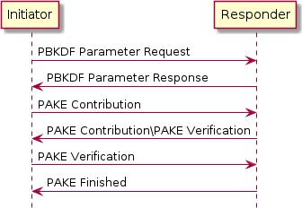
Figure 14. Overview of the PASE Protocol
The Commissioner is the Initiator and the Commissionee is the Responder.
It is assumed that the initiator has somehow obtained the passcode and that the responder has the relevant Crypto_PAKEValues_Responder corresponding to the passcode before starting a PASE session establishment protocol.
Protocol Details
Message format
All PASE messages SHALL be structured as specified in Section 4.4, “Message Frame Format”. All PASE messages are unsecured at the message layer:
The Session ID field SHALL be set to 0.
The Session Type bits of the Security Flags SHALL be set to 0.
The S Flag and DSIZ fields of the Message Flags SHALL be set to 0.
For each PASE message, the application payload is the TLV encoding of the message structure as defined below:
Table 22. PASE Messages
Message Name
Payload TLV Encoding
PBKDFParamRequest
pbkdfparamreq-struct
PBKDFParamResponse
pbkdfparamresp-struct
Pake1
pake-1-struct
Pake2
pake-2-struct
Pake3
pake-3-struct
Message Name
Payload TLV Encoding
PakeFinished
N/A (encoded via StatusReport)
The other fields of the Message format are not specific to the PASE messages.
For all TLV-encoded PASE messages, any context-specific tags not listed in the associated TLV schemas SHALL be reserved for future use, and SHALL be silently ignored if seen by a recipient which cannot understand them.
Message Exchange
The PBKDFParamRequest, PBKDFParamResponse, Pake1, Pake2, Pake3, and PakeFinished of a distinct session establishment are part of the same message exchange. The initiator and responder SHALL NOT send encrypted application data in the newly established session until PakeFinished is received by the initiator within the unencrypted session used for establishment.
Each message SHALL use PROTOCOL_ID_SECURE_CHANNEL as Protocol ID and the corresponding Protocol Opcode as defined in Table 17, “Secure Channel Protocol Opcodes”.
The flags of the Exchange Flags of the Protocol Header are defined as follows per PASE message:
Message
I Flag
PBKDFParamRequest
1
PBKDFParamResponse
0
Pake1
1
Pake2
0
Pake3
1
All PASE messages SHALL be sent reliably. This may be implicit (e.g. TCP) or explicit (e.g. MRP reliable messaging) in the underlying transport.

CAUTION
TODO: if MRP is used, it may be the case that PASE should define additional parameters for the MRP layer (e.g. the timeouts on the various PASE messages). This is to be handled with issue #2103.
The other fields of the Protocol Header are not specific to the PASE messages.
PBKDFParamRequest
This message serves to request the PBKDF parameters, with a payload that follows this TLV schema:

pbkdfparamreq-struct => STRUCTURE [ tag-order ]
{
initiatorRandom [1] : OCTET STRING [ length 32 ], initiatorSessionId [2] : UNSIGNED INTEGER [ range 16-bits ], passcodeId [3] : UNSIGNED INTEGER [ length 16-bits ], hasPBKDFParameters [4] : BOOLEAN,
initiatorSEDParams [5, optional] : sed-parameter-struct
}
The initiator SHALL generate a random number InitiatorRandom = Crypto_DRBG(len = 32 * 8).
The initiator SHALL generate a session identifier (InitiatorSessionId) for subsequent identification of this session. The InitiatorSessionId field SHALL NOT overlap with any other existing PASE or CASE session identifier in use by the responder. See Section 4.12.1.4, “Choosing Secure Unicast Session Identifiers” for more details. The initiator SHALL set the Local Session Identifier in the Session Context to the value InitiatorSessionId.
The initiator SHALL choose a passcode identifier (PasscodeId) corresponding to a particular PAKE passcode verifier installed on the responder. A value of 0 for the passcodeID SHALL correspond to the PAKE passcode verifier for the currently-open commissioning window, if any. Non-zero values are reserved for future use. For example, for initial commissioning, the verifier would be the built-in verifier matching the Onboarding Payload's passcode or, equivalently, the multi-fabric Basic Commissioning Method passcode if that method is supported. For the multi- fabric Enhanced Commissioning Method, the verifier would match the verifier provided through the OpenCommissioningWindow command.
The initiator SHALL indicate whether the PBKDF parameters (salt and iterations) are known for the particular passcodeId (for example from the QR code) by setting HasPBKDFParameters. If HasPBKDFParameters is set to True, the responder SHALL NOT return the PBKDF parameters. If HasPBKDFParameters is set to False, the responder SHALL return the PBKDF parameters.

PBKDFParamRequest =
{
initiatorRandom (1) = InitiatorRandom, initiatorSessionId (2) = InitiatorSessionId, passcodeID (3) = PasscodeId, hasPBKDFParameters (4) = HasPBKDFParameters,
}
The initiator SHALL send a message with the appropriate Protocol Id and Protocol Opcode from Table 17, “Secure Channel Protocol Opcodes” whose payload is the TLV-encoded pbkdfparamreq-struct PBKDFParamRequest with an anonymous tag for the outermost struct.
PBKDFParamResponse

pbkdfparamresp-struct => STRUCTURE [ tag-order ]
{
initiatorRandom [1] : OCTET STRING [ length 32 ], responderRandom [2] : OCTET STRING [ length 32 ], responderSessionId [3] : UNSIGNED INTEGER [ range 16-bits ], pbkdf_parameters [4] : Crypto_PBKDFParameterSet, responderSEDParams [5, optional] : sed-parameter-struct
}
On receipt of PBKDFParamRequest, the responder SHALL:
Verify passcodeID is set to 0. If verification fails, the responder SHALL send a status report: StatusReport(GeneralCode: FAILURE, ProtocolId: SECURE_CHANNEL, ProtocolCode: INVALID_PARAMETER) and perform no further processing.
Generate a random number ResponderRandom = Crypto_DRBG(len = 32 * 8).
Generate a session identifier (ResponderSessionId) for subsequent identification of this session. The ResponderSessionId field SHALL NOT overlap with any other existing PASE or CASE session identifier in use by the responder. See Section 4.12.1.4, “Choosing Secure Unicast Session Identifiers” for more details. The responder SHALL set the Local Session Identifier in the Session Context to the value ResponderSessionId.
Set the Peer Session Identifier in the Session Context to the value
PBKDFParamRequest.initiatorSessionId.
Construct the appropriate Crypto_PBKDFParameterSet (PBKDFParameters). If PBKDFParamRequest.hasPBKDFParameters is True the responder SHALL NOT include the PBKDF parameters (i.e. salt and iteration count) in the Crypto_PBKDFParameterSet. If Msg1.hasPBKDFParameters is False the responder SHALL include the PBKDF parameters (i.e. salt and iteration count) in the Crypto_PBKDFParameterSet.

PBKDFParamResponse =
{
initiatorRandom (1) = PBKDFParamRequest.initiatorRandom, responderRandom (2) = ResponderRandom, responderSessionId (3) = ResponderSessionId, pbkdf_parameters (4) = PBKDFParameters
}
Send a message with the appropriate Protocol Id and Protocol Opcode from Table 17, “Secure Channel Protocol Opcodes” whose payload is the TLV-encoded pbkdfparamresp-struct PBKDFParamResponse with an anonymous tag for the outermost struct.
Pake1

pake-1-struct => STRUCTURE [ tag-order ]
{
pA [1] : OCTET STRING [ length CRYPTO_PUBLIC_KEY_SIZE_BYTES ],
}
On receipt of PBKDFParamResponse, the initiator SHALL:
Set the Peer Session Identifier in the Session Context to the value
PBKDFParamResponse.responderSessionId.
Generate the Crypto_PAKEValues_Initiator according to the PBKDFParamResponse.pbkdf_parameters
Using Crypto_PAKEValues_Initiator, generate pA := Crypto_pA(Crypto_PAKEValues_Initiator)

Pake1 =
{
pA (1) = pA,
}
Send a message with the appropriate Protocol Id and Protocol Opcode from Table 17, “Secure Channel Protocol Opcodes” whose payload is the TLV-encoded pake-1-struct Pake1 with an anonymous tag for the outermost struct.

pake-2-struct => STRUCTURE [ tag-order ]
{
pB [1] : OCTET STRING [ length CRYPTO_PUBLIC_KEY_SIZE_BYTES ], cB [2] : OCTET STRING [ length CRYPTO_HASH_LEN_BYTES],
}
Pake2
On receipt of Pake1, the responder SHALL:
Compute pB := Crypto_pB(Crypto_PAKEValues_Responder) using the passcode verifier indicated in
PBKDFParamRequest
Compute TT := Crypto_Transcript(PBKDFParamRequest, PBKDFParamResponse, Pake1.pA, pB)
Compute (cA, cB, Ke) := Crypto_P2(TT, Pake1.pA, pB)

Pake2 =
{
pB (1) = pB,
cB (2) = cB,
}
Send a message with the appropriate Protocol Id and Protocol Opcode from Table 17, “Secure Channel Protocol Opcodes” whose payload is the TLV-encoded pake-2-struct Pake2 with an anonymous tag for the outermost struct.

pake-3-struct => STRUCTURE [ tag-order ]
{
cA [1] : OCTET STRING [length CRYPTO_HASH_LEN_BYTES],
}
Pake3
On receipt of Pake2, the initiator SHALL:
Compute TT := Crypto_Transcript(PBKDFParamRequest, PBKDFParamResponse, Pake1.pA, Pake2.pB)
Compute (cA, cB, Ke) := Crypto_P2(TT, Pake1.pA, Pake2.pB)
Verify Pake2.cB against cB. If verification fails, the initiator SHALL send a status report: StatusReport(GeneralCode: FAILURE, ProtocolId: SECURE_CHANNEL, ProtocolCode: INVALID_PARAMETER) and perform no further processing.

Pake3 =
{
cA (1) = cA,
}
Send a message with the appropriate Protocol Id and Protocol Opcode from Table 17, “Secure Channel Protocol Opcodes” whose payload is the TLV-encoded pake-3-struct Pake3 with an anonymous tag for the outermost struct.
The initiator SHALL NOT send any encrypted application data until it receives PakeFinished
from the responder.
On reception of Pake3, the responder SHALL:
Verify Pake3.cA against cA. If verification fails, the responder SHALL send a status report: StatusReport(GeneralCode: FAILURE, ProtocolId: SECURE_CHANNEL, ProtocolCode: INVALID_PARAMETER) and perform no further processing.
The responder SHALL set SessionTimestamp to a timestamp from a clock which would allow for the eventual determination of the last session use relative to other sessions.
The responder SHALL encode and send PakeFinished.
PakeFinished
To indicate the successful completion of the protocol, the responder SHALL send a status report: StatusReport(GeneralCode: SUCCESS, ProtocolId: SECURE_CHANNEL, ProtocolCode: SESSION_ESTABLISHMENT_SUCCESS).
The initiator SHALL set SessionTimestamp to a timestamp from a clock which would allow for the eventual determination of the last session use relative to other sessions.
Session Encryption Keys
After verification of Pake3, each party can compute their sending and receiving session keys as

byte SEKeys_Info[] = /* "SessionKeys" */
{0x53, 0x65, 0x73, 0x73, 0x69, 0x6f, 0x6e, 0x4b, 0x65, 0x79, 0x73}
I2RKey || R2IKey || AttestationChallenge =
Crypto_KDF (
inputKey = Ke, salt = [],
info = SEKeys_Info,
len = 3 * CRYPTO_SYMMETRIC_KEY_LENGTH_BITS
)
described below:
Each key is exactly CRYPTO_SYMMETRIC_KEY_LENGTH_BITS bits.
The initiator SHALL use I2RKey to encrypt and integrity protect messages and the `R2IKey' to decrypt and verify messages.
The responder SHALL use R2IKey to encrypt and integrity protect messages and the `I2RKey' to decrypt and verify messages.
The AttestationChallenge SHALL only be used as a challenge during device attestation. See Section 6.2.3, “Device Attestation Procedure” for more details.
Upon initial installation of the new PASE Session Keys:
The Node SHALL initialize its Local Message Counter in the Session Context per Section 4.5.1.1, “Message Counter Initialization”.
The Node SHALL initialize the Message Reception State in the Session Context` and set the synchronized max_message_counter of the peer to 0.
where || indicates message concatenation and [] a zero-length array.
Certificate Authenticated Session Establishment (CASE)
This section describes a certificate-authenticated session establishment (CASE) protocol using Node Operational credentials. This session establishment mechanism provides an authenticated key exchange between exactly two peers while maintaining privacy of each peer. A resumption mechanism allows bootstrapping a new session from a previous one, dramatically reducing the computation required as well as reducing the number of messages exchanged.
Protocol Overview
This session establishment protocol provides a means to:
Mutually authenticate both peer Nodes
Generate cryptographic keys to secure subsequent communication within a session
Exchange operational parameters for the session, such as Session Identifier and MRP parameters
The cryptographic protocol mirrors the [SIGMA] protocol and uses the Identity Protection Key (IPK) to provide better identity protection. Briefly, the protocol will:
Exchange ephemeral elliptic curve public keys (Sigma1.initiatorEphPubKey and
Sigma2.responderEphPubKey) to generate a shared secret
Exchange certificates to prove identities (Sigma2.encrypted2.responderNOC and
Sigma3.encrypted3.initiatorNOC)
Prove possession of the NOC private key by signing the ephemeral keys and NOC (sigma-2- tbsdata and sigma-3-tbsdata)
The basic protocol can be achieved within 2 round trips as shown below:
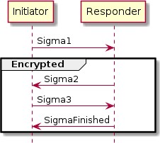
Figure 15. Basic Session Establishment
Session Resumption
The protocol also provides a means to quickly resume a session using a previously established session. Resumption does not require expensive signature creation and verification which significantly reduces the computation time. Because of this, resumption is favoured for low- powered devices when applicable. Session resumption SHOULD be used by initiators when the necessary state is known to the initiator.
The nomenclature Sigma1 with Resumption in the following subsections implies a Sigma1 message with both the optional resumptionID and initiatorResumeMIC fields populated in sigma-1-struct.
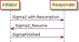
Figure 16. Session Resumption
In the case where a Responder is not able to resume a session as requested by a Sigma1 with
Resumption, the information included in the Sigma1 with Resumption message SHALL be processed as a Sigma1 message without any resumption fields to construct a Sigma2 message and continue the standard session establishment protocol without resumption.
To make the resumption succeed, both the Initiator and the Responder SHALL have remembered the SharedSecret they have computed during the previous execution of the CASE session establishment. It SHALL be that SharedSecret that is used to compute the resumption ID.
Session Resumption State
To perform session resumption, the following state from the previous session context must be known to the initiator and responder:
SharedSecret
Local Fabric Index
Peer Node ID
Peer CASE Authenticated Tags
ResumptionID
Protocol Details
Message format
All CASE messages SHALL be structured as specified in Section 4.4, “Message Frame Format”. All CASE messages are unsecured at the message layer:
The Session ID field SHALL be set to 0.
The Session Type bits of the Security Flags SHALL be set to 0.
The S Flag and DSIZ fields of the Message Flags SHALL be set to 0.
For each CASE message, the application payload is the TLV encoding of the message structure as defined below:
Table 23. CASE Messages
Message Name
Payload TLV Encoding
Sigma1
sigma-1-struct
Sigma2
sigma-2-struct,
Sigma3
sigma-3-struct,
Sigma2_Resume
sigma-2-resume-struct,
SigmaFinished
N/A (encoded via StatusReport)
The other fields of the Message format are not specific to the CASE messages.
Message Exchange
The Sigma1, Sigma2, Sigma3, and SigmaFinished of a distinct session establishment are part of the same message exchange. The Sigma1 with resumption, Sigma2_Resume and SigmaFinished of a distinct session resumption are part of the same message exchange. The Sigma1 with resumption, Sigma2, Sigma3 and SigmaFinished of a distinct session resumption that failed to perform the resumption are part of the same message exchange.
Each message SHALL use PROTOCOL_ID_SECURE_CHANNEL as Protocol ID and the corresponding Protocol Opcode as defined in Table 17, “Secure Channel Protocol Opcodes”.
The Exchange Flags of the Protocol Header are defined as follows per CASE message:
Message
I Flag
CASE Sigma1
1
CASE Sigma2
0
CASE Sigma3
1
CASE Sigma2_Resume
0
For the SigmaFinished message the value of the I Flag is set depending on whether the status message is sent by the Initiator or the Responder.
All CASE messages SHALL be sent reliably. This may be implicit (e.g. TCP) or explicit (e.g. MRP reliable messaging) in the underlying transport.
The other fields of the Exchange format are not specific to the CASE messages.
Generate and Send Sigma1

sigma-1-struct => STRUCTURE [ tag-order ]
{
initiatorRandom [1] : OCTET STRING [ length 32 ], initiatorSessionId [2] : UNSIGNED INTEGER [ range 16-bits ], destinationId [3] : destination-identifier, initiatorEphPubKey [4] : ec-pub-key,
initiatorSEDParams [5, optional] : sed-parameter-struct, resumptionID [6, optional] : OCTET STRING [ length 16 ], initiatorResumeMIC [7, optional] : OCTET STRING [ length
CRYPTO_AEAD_MIC_LENGTH_BYTES ]
}
The initiator encodes and sends a Sigma1 message, with a payload that follows this TLV schema:
The initiator SHALL generate a random number InitiatorRandom = Crypto_DRBG(len = 32 * 8).
The initiator SHALL generate a session identifier (InitiatorSessionId) for subsequent identification of this session. The InitiatorSessionId field SHALL NOT overlap with any other existing PASE or CASE session identifier in use by the initiator. See Section 4.12.1.4, “Choosing Secure Unicast Session Identifiers” for more details.
The initiator SHALL generate a destination identifier (DestinationId) according to Destination Identifier to enable the responder to properly select a mutual Fabric and trusted root for the secure session.
The initiator SHALL generate an ephemeral key pair InitiatorEphKeyPair = Crypto_GenerateKeypair().
The initiator MAY encode any relevant MRP parameters.
Any context-specific tags not listed in the above TLV schemas SHALL be reserved for future use, and SHALL be silently ignored if seen by a responder which cannot understand them.
If the initiator is resuming a session from a previous execution of the CASE with the same peer, the initiator SHALL:
Note the ResumptionID of the previous session.
Generate the S1RK key.

byte Resume1MIC_P[] = {} byte Resume1MIC_A[] = {}
byte Resume1MIC_Nonce[13] = /* "NCASE_SigmaR1" */
{0x4e, 0x43, 0x41, 0x53, 0x45, 0x5f, 0x53, 0x69, 0x67, 0x6d, 0x61, 0x53, 0x31}
InitiatorResume1MIC = Crypto_AEAD_GenerateEncrypt( K = S1RK,
P = Resume1MIC_P, A = Resume1MIC_A,
N = Resume1MIC_Nonce
)
Generate the initiatorResumeMIC using the SharedSecret from the previous session:

Msg1 =
{
initiatorRandom (1) = InitiatorRandom, initiatorSessionId (2) = InitiatorSessionId, destinationId (3) = DestinationId,
initiatorEphPubKey (4) = InitiatorEphKeyPair.publicKey initiatorSEDParams (5) = sed-parameter-struct (optional), resumptionID (6) = ResumptionID (optional, only present if performing
resumption),
initiatorResumeMIC (7) = InitiatorResume1MIC (optional, only present if performing resumption)
}
The initiator SHALL send a message with Secure Channel Protocol ID and Sigma1 Protocol Opcode from Table 17, “Secure Channel Protocol Opcodes” whose payload is the TLV-encoded Sigma1 Msg1 with an anonymous tag for the outermost struct.
Validate Sigma1
On receipt of Msg1, the responder SHALL perform the following:
If Msg1 contains either a resumptionID or an initiatorResumeMIC field but not both, the responder SHALL send a status report: StatusReport(GeneralCode: FAILURE, ProtocolId: SECURE_CHANNEL, ProtocolCode: INVALID_PARAMETER) and perform no further processing.
Set the Peer Session Identifier in the Session Context to the value Msg1.initiatorSessionId.
If Msg1 contains both the resumptionID and initiatorResumeMIC fields, the responder SHALL search for an existing session that has a Resumption ID equal to the incoming resumptionID. If a single such session exists, the responder SHALL follow the steps in Section 4.13.2.3.10, “Validate Sigma1 with Resumption” rather than continue the steps outlined in Section 4.13.2.3.5, “Validate Sigma1 Destination ID”.
If Msg1 does not contain a resumptionID and initiatorResumeMIC field, the responder SHALL continue the steps in Section 4.13.2.3.5, “Validate Sigma1 Destination ID”.
Validate Sigma1 Destination ID
The responder SHALL validate the incoming destinationId:
The responder SHALL traverse all its installed Node Operational Certificates (NOC), gathering the associated trusted roots' public keys from the associated chains and SHALL generate a candidateDestinationId based on the procedure in Section 4.13.2.4.1, “Destination Identifier” for that tuple of <Root Public Key, Fabric ID, Node ID>.
The responder SHALL verify that the incoming destinationId matches one of the candidateDestinationId generated above. Upon such a match, the associated trusted root, Fabric ID, Node ID and IPK SHALL be recorded for subsequent use.
Note that at the initiator, only the current Epoch Key for the IPK will have been used. At the receiver, several IPK Epoch Keys may be installed, requiring several candidateDestinationId to be computed, one per available IPK Operational Key, per NOC.
If there is no candidateDestinationId matching the incoming destinationId, the responder SHALL send a status report: StatusReport(GeneralCode: FAILURE, ProtocolId: SECURE_CHANNEL, ProtocolCode: NO_SHARED_TRUST_ROOTS) and perform no further processing.
Otherwise, if a match was found for the destinationId, the matched NOC, ICAC (if present), and associated trusted root SHALL be used for selection of the responderNOC and responderICAC in the steps for Sigma2.
Generate and Send Sigma2
If validation is successful, the responder encodes and sends a Sigma2 message.
sigma-2-tbsdata => STRUCTURE [ tag-order ]
{
responderNOC [1] : OCTET STRING, responderICAC [2, optional] : OCTET STRING, responderEphPubKey [3] : ec-pub-key, initiatorEphPubKey [4] : ec-pub-key,
}
sigma-2-tbedata => STRUCTURE [ tag-order ]
{
responderNOC [1] : OCTET STRING, responderICAC [2, optional] : OCTET STRING, signature [3] : ec-signature,
resumptionID [4] : OCTET STRING [ length 16 ],
}
sigma-2-struct => STRUCTURE [ tag-order ]
{
responderRandom [1] : OCTET STRING [ length 32 ], responderSessionId [2] : UNSIGNED INTEGER [ range 16-bits ], responderEphPubKey [3] : ec-pub-key,
encrypted2 [4] : OCTET STRING, responderSEDParams [5, optional] : sed-parameter-struct
}


NOTE
sigma-2-tbsdata is NOT transmitted but is instead signed; the signature will be encrypted and transmitted.
The responder SHALL generate a random resumption ID ResumptionID = Crypto_DRBG(len = 16 * 8).
The responder SHALL set the Resumption ID in the Session Context to the value ResumptionID.
The responder SHALL use the Node Operational Key Pair ResponderNOKeyPair, responderNOC, and responderICAC (if present) corresponding to the NOC obtained in Section 4.13.2.3.4, “Validate Sigma1”.
The responder SHALL generate an ephemeral key pair ResponderEphKeyPair = Crypto_GenerateKeypair().

SharedSecret = Crypto_ECDH(
privateKey = ResponderEphKeyPair.privateKey, publicKey = Msg1.initiatorEphPubKey,
)
The responder SHALL generate a shared secret:
The responder SHALL encode the following items as a sigma-2-tbsdata with an anonymous tag:
responderNOC as a matter-certificate
responderICAC (if present) as a matter-certificate
ResponderEphKeyPair.publicKey
Msg1.initiatorEphPubKey
ResumptionID

TBSData2Signature = Crypto_Sign( message = sigma-2-tbsdata,
privateKey = ResponderNOKeyPair.privateKey
)
The responder SHALL generate a signature:
The responder SHALL encode the following items as a sigma-2-tbedata, where the encoding of responderNOC and responderICAC items SHALL be byte-for-byte identical to the encoding in sigma- 2-tbsdata:
responderNOC as a matter-certificate. This encoding SHALL be byte-for-byte identical to the encoding in sigma-2-tbsdata.
responderICAC (if present) as a matter-certificate. This encoding SHALL be byte-for-byte identical to the encoding in sigma-2-tbsdata.
TBSData2Signature
The responder SHALL generate the S2K key.

byte TBEData2_A[] = {}
byte TBEData2_Nonce[13] = /* "NCASE_Sigma2N" */
{0x4e, 0x43, 0x41, 0x53, 0x45, 0x5f, 0x53, 0x69, 0x67, 0x6d, 0x61, 0x32, 0x4e}
TBEData2Encrypted = Crypto_AEAD_GenerateEncrypt( K = S2K,
P = TBEData2,
A = TBEData2_A,
N = TBEData2_Nonce
)
The responder SHALL generate the encrypted and integrity protected data:
The responder SHALL generate a random number Random = Crypto_DRBG(len = 32 * 8).
The responder SHALL generate a session identifier (ResponderSessionId) for subsequent identification of this secured session. The ResponderSessionId field SHALL NOT overlap with any other existing PASE or CASE session identifier in use by the responder. See Section 4.12.1.4, “Choosing Secure Unicast Session Identifiers” for more details. The responder SHALL set the Local Session Identifier in the Session Context to the value ResponderSessionId.
The responder SHALL use the Fabric IPK configured as described in Section 4.13.2.6.1, “Identity Protection Key (IPK)”.
Any context-specific tags not listed in the above TLV schemas SHALL be reserved for future use, and SHALL be silently ignored if seen by an initiator which cannot understand them.

Msg2 =
{
responderRandom (1) = Random, responderSessionId (2) = ResponderSessionId,
responderEphPubKey (3) = ResponderEphKeyPair.publicKey, encrypted2 (4) = TBEData2Encrypted,
responderSEDParams (5) = sed-parameter-struct (optional)
}
The responder SHALL send a message with Secure Channel Protocol ID and Sigma2 Protocol Opcode from Table 17, “Secure Channel Protocol Opcodes” whose payload is the TLV-encoded Sigma2 Msg2 with an anonymous tag for the outermost struct.
Validate Sigma2
On receipt of Msg2, the initiator SHALL perform the following:

SharedSecret = Crypto_ECDH(
privateKey = InitiatorEphKeyPair.privateKey, publicKey = Msg2.responderEphPubKey,
)
The initiator SHALL generate a shared secret:
The initiator SHALL generate the S2K key.

byte TBEData2_A[] = {}
byte TBEData2_Nonce[13] = /* "NCASE_Sigma2N" */
{0x4e, 0x43, 0x41, 0x53, 0x45, 0x5f, 0x53, 0x69, 0x67, 0x6d, 0x61, 0x32, 0x4e}
Success, TBEData2 = Crypto_AEAD_DecryptVerify( K = S2K,
C = Msg2.encrypted2, A = TBEData2_A,
N = TBEData2_Nonce
)
The initiator SHALL generate the decrypted data:
If the value of Success is FALSE, the initiator SHALL send a status report: StatusReport(GeneralCode: FAILURE, ProtocolId: SECURE_CHANNEL, ProtocolCode: INVALID_PARAMETER) and perform no further processing.
The initiator SHALL verify that the NOC in TBEData2.responderNOC and ICAC in
TBEData2.responderICAC (if present) fulfills the following constraints:
The Fabric ID and Node ID SHALL match the intended identity of the receiver Node, as included in the computation of the Destination Identifier when generating Sigma1.
If an ICAC is present, and it contains a Fabric ID in its subject, then it SHALL match the FabricID in the NOC leaf certificate.
The certificate chain SHALL chain back to the Trusted Root CA Certificate TrustedRCAC whose public key was used in the computation of the Destination Identifier when generating Sigma1.
All the elements in the certificate chain SHALL respect the Matter Certificate DN Encoding Rules, including range checks for identifiers such as Fabric ID and Node ID.
If any of the validations from the previous step fail, the initiator SHALL send a status report: StatusReport(GeneralCode: FAILURE, ProtocolId: SECURE_CHANNEL, ProtocolCode: INVALID_PARAMETER) and perform no further processing.
The initiator SHALL verify TBEData2.responderNOC using:
Success = Crypto_VerifyChain(certificates = [TBEData2.responderNOC,
TBEData2.responderICAC, TrustedRCAC]), when TBEData2.responderICAC is present, or
Success = Crypto_VerifyChain(certificates = [TBEData2.responderNOC, TrustedRCAC]), when
TBEData2.responderICAC is not present.
If the value of Success is FALSE, the initiator SHALL send a status report: StatusReport(GeneralCode: FAILURE, ProtocolId: SECURE_CHANNEL, ProtocolCode: INVALID_PARAMETER) and perform no further processing.
The initiator SHALL encode the following items as a sigma-2-tbsdata with an anonymous tag:
responderNOC as copied from TBEData2
responderICAC (if present) as copied from TBEData2
Msg2.responderEphPubKey
InitiatorEphKeyPair.publicKey

Success = Crypto_Verify(
publicKey = Public key obtained from responderNOC, message = sigma-2-tbsdata,
signature = TBEData2.signature
)
The initiator SHALL verify TBEData2.signature (see RFC 5280):
If the value of Success is FALSE, the initiator SHALL send a status report: StatusReport(GeneralCode: FAILURE, ProtocolId: SECURE_CHANNEL, ProtocolCode: INVALID_PARAMETER) and perform no further processing.
Set the Resumption ID in the Session Context to the value TBEData2.resumptionID.
Set the Peer Session Identifier in the Session Context to the value Msg2.responderSessionId.
Generate and Send Sigma3

sigma-3-tbsdata => STRUCTURE [ tag-order ]
{
initiatorNOC [1] : OCTET STRING, initiatorICAC [2, optional] : OCTET STRING, initiatorEphPubKey [3] : ec-pub-key, responderEphPubKey [4] : ec-pub-key,
}
sigma-3-tbedata => STRUCTURE [ tag-order ]
{
initiatorNOC [1] : OCTET STRING, initiatorICAC [2, optional] : OCTET STRING, signature [3] : ec-signature,
}
sigma-3-struct => STRUCTURE [ tag-order ]
{
encrypted3 [1] : OCTET STRING,
}
If validation is successful, the initiator encodes and sends a Sigma3 message.

NOTE
sigma-3-tbsdata is NOT transmitted but is instead signed; the signature will be encrypted and transmitted.
The initiator SHALL select its Node Operational Key Pair InitiatorNOKeyPair, Node Operational Certificates initiatorNOC and initiatorICAC (if present), and Trusted Root CA Certificate TrustedRCAC corresponding to the chosen Fabric as determined by the Destination Identifier from Sigma1.
The initiator SHALL encode the following items as a sigma-3-tbsdata with an anonymous tag:
initiatorNOC as a matter-certificate
initiatorICAC (if present) as a matter-certificate
InitiatorEphKeyPair.publicKey
Msg2.responderEphPubKey

TBSData3Signature = Crypto_Sign( message = sigma-3-tbsdata,
privateKey = InitiatorNOKeyPair.privateKey
)
The initiator SHALL generate a signature:
The initiator SHALL encode the following items as a sigma-3-tbedata:
initiatorNOC as a matter-certificate. This encoding SHALL be byte-for-byte identical to the
encoding in sigma-3-tbsdata.
initiatorICAC (if present) as a matter-certificate. This encoding SHALL be byte-for-byte identical to the encoding in sigma-3-tbsdata.
TBSData3Signature
The initiator SHALL generate the S3K key.

byte TBEData3_A[] = {}
byte TBEData3_Nonce[13] = /* "NCASE_Sigma3N" */
{0x4e, 0x43, 0x41, 0x53, 0x45, 0x5f, 0x53, 0x69, 0x67, 0x6d, 0x61, 0x33, 0x4e}
TBEData3Encrypted = Crypto_AEAD_GenerateEncrypt( K = S3K,
P = TBEData3,
A = TBEData3_A,
N = TBEData3_Nonce
)
The initiator SHALL generate the encrypted and integrity protected data:
Any context-specific tags not listed in the above TLV schemas SHALL be reserved for future use, and SHALL be silently ignored if seen by a responder which cannot understand them.
The initiator SHALL send a message with Secure Channel Protocol ID and Sigma3 Protocol Opcode from Table 17, “Secure Channel Protocol Opcodes” whose payload is the TLV-encoded Sigma3 Msg3 = { encrypted3 (1) = TBEData3Encrypted } with an anonymous tag for the outermost struct.
The initiator SHALL generate the session encryption keys using the method described in Section 4.13.2.6.6, “Session Encryption Keys”.
Validate Sigma3
On receipt of Msg3, the responder SHALL perform the following:
The responder SHALL generate the S3K key.
The responder SHALL generate the decrypted data:

byte TBEData3_A[] = {}
byte TBEData3_Nonce[13] = /* "NCASE_Sigma3N" */
{0x4e, 0x43, 0x41, 0x53, 0x45, 0x5f, 0x53, 0x69, 0x67, 0x6d, 0x61, 0x33, 0x4e}
Success, TBEData3 = Crypto_AEAD_DecryptVerify( K = S3K,
C = Msg3.encrypted3, A = TBEData3_A,
N = TBEData3_Nonce
)
If the value of Success is FALSE, the responder SHALL send a status report: StatusReport(GeneralCode: FAILURE, ProtocolId: SECURE_CHANNEL, ProtocolCode: INVALID_PARAMETER) and perform no further processing.
The responder SHALL verify that the NOC in TBEData3.responderNOC and the ICAC in
TBEData3.responderICAC fulfill the following constraints:
The Fabric ID SHALL match the Fabric ID matched during processing of the Destination Identifier after receiving Sigma1.
If an ICAC is present, and it contains a Fabric ID in its subject, then it SHALL match the FabricID in the NOC leaf certificate.
The certificate chain SHALL chain back to the Trusted Root CA Certificate TrustedRCAC whose public key was matched during processing of the Destination Identifier after receiving Sigma1.
All the elements in the certificate chain SHALL respect the Matter Certificate DN Encoding Rules, including range checks for identifiers such as Fabric ID and Node ID.
If any of the validations from the previous step fail, the responder SHALL send a status report: StatusReport(GeneralCode: FAILURE, ProtocolId: SECURE_CHANNEL, ProtocolCode: INVALID_PARAMETER) and perform no further processing.
The responder SHALL verify TBEData3.initiatorNOC using:
Success = Crypto_VerifyChain(certificates = [TBEData3.initiatorNOC,
TBEData3.initiatorICAC, TrustedRCAC]), when TBEData3.initiatorICAC is present, or
Success = Crypto_VerifyChain(certificates = [TBEData3.initiatorNOC, TrustedRCAC]), when
TBEData3.initiatorICAC is not present.
If the value of Success is FALSE, the responder SHALL send a status report: StatusReport(GeneralCode: FAILURE, ProtocolId: SECURE_CHANNEL, ProtocolCode: INVALID_PARAMETER_) and perform no further processing.
The responder SHALL encode the following items as a sigma-3-tbsdata with an anonymous tag:
initiatorNOC as copied from TBEData3
initiatorICAC (if present) as copied from TBEData3
Msg1.initiatorEphPubKey
ResponderEphKeyPair.publicKey

Success = Crypto_Verify(
publicKey= public key obtained from initiatorNOC, message = sigma-3-tbsdata,
signature = TBEData3.signature
)
The responder SHALL verify TBEData3.signature (see RFC 5280):
If the value of Success is FALSE, the responder SHALL send a status report: StatusReport(GeneralCode: FAILURE, ProtocolId: SECURE_CHANNEL, ProtocolCode: INVALID_PARAMETER) and perform no further processing.
The responder SHALL generate the session keys as described in Section 4.13.2.6.6, “Session Encryption Keys”.
The responder SHALL initialize its Local Message Counter in the Session Context per Section 4.5.1.1, “Message Counter Initialization”.
The responder SHALL initialize the Message Reception State in the Session Context` and set the synchronized max_message_counter of the peer to 0.
The responder SHALL set SessionTimestamp to a timestamp from a clock which would allow for the eventual determination of the last session use relative to other sessions.
The responder SHALL encode and send SigmaFinished.
Validate Sigma1 with Resumption
The responder SHALL continue validating the Sigma1 message Msg1 as follows:
Obtain the SharedSecret from the Section 4.12.2.1, “Secure Session Context” of the resumed session.
Generate the S1RK key.

byte Resume1MIC_A[] = {}
byte Resume1MIC_Nonce[13] = /* "NCASE_SigmaR1" */
{0x4e, 0x43, 0x41, 0x53, 0x45, 0x5f, 0x53, 0x69, 0x67, 0x6d, 0x61, 0x53, 0x31}
Success, Resume1MICPayload = Crypto_AEAD_DecryptVerify( K = S1RK,
C = Msg1.sigma1ResumeMIC, A = Resume1MIC_A,
N = Resume1MIC_Nonce
)
Verify the Resume1MIC by decrypting the following values:
If the value of Success is FALSE, the responder SHALL continue processing Sigma1 as if it didn’t include any resumption information by continuing the steps in Section 4.13.2.3.5, “Validate Sigma1 Destination ID”.
If the value of Success is TRUE, the responder SHALL:
Set the Peer Session Identifier in the in the Session Context to the value
Msg1.initiatorSessionId.
Send a Sigma2_Resume message.
Generate and Send Sigma2_Resume

sigma-2-resume-struct => STRUCTURE [ tag-order ]
{
resumptionID [1] : OCTET STRING [ length 16 ], sigma2ResumeMIC [2] : OCTET STRING [ length 16 ], responderSessionID [3] : UNSIGNED INTEGER [ range 16-bits ], responderSEDParams [4, optional] : sed-parameter-struct
}
The responder SHALL encode and send a Sigma2_Resume message in response to a valid Sigma1 with response.
The responder SHALL generate a new resumption ID ResumptionID = Crypto_DRBG(len = 128).
The responder SHALL generate a session identifier (ResponderSessionId) for subsequent identification of this session. The ResponderSessionId field SHALL NOT overlap with any other existing PASE or CASE session identifier in use by the responder. See Section 4.12.1.4, “Choosing Secure Unicast Session Identifiers” for more details. The responder SHALL set the Local Session Identifier in the Session Context to the value ResponderSessionId.
The responder SHALL generate the S2RK key.

byte Resume2MIC_P[] = {} byte Resume2MIC_A[] = {}
byte Resume2MIC_Nonce[13] = /* "NCASE_SigmaR2" */
{0x4e, 0x43, 0x41, 0x53, 0x45, 0x5f, 0x53, 0x69, 0x67, 0x6d, 0x61, 0x53, 0x32}
Resume2MIC = Crypto_AEAD_GenerateEncrypt( K = S2RK,
P = Resume2MIC_P, A = Resume2MIC_A,
N = Resume2MIC_Nonce
)
The responder SHALL generate a resumption MIC:
Any context-specific tags not listed in the above TLV schemas SHALL be reserved for future use, and SHALL be silently ignored if seen by an initiator which cannot understand them.
The responder SHALL send a message with the Secure Channel Protocol ID and Sigma2Resume Protocol Opcode from Table 17, “Secure Channel Protocol Opcodes” whose payload is the TLV- encoded Sigma2_Resume ResumeMsg2 with an anonymous tag for the outermost struct.

ResumeMsg2 =
{
resumptionID (1) = ResumptionID, sigma2ResumeMIC (2) = ResumeMIC2, responderSessionID (3) = ResponderSessionId,
responderSEDParams (4) = sed-parameter-struct (optional)
}
The responder SHALL generate the session keys as described in Section 4.13.2.6.7, “Resumption Session Encryption Keys”.
Validate Sigma2_Resume
On receipt of ResumeMsg2, the initiator SHALL perform the following:
The initiator SHALL generate the S2RK key.

byte Resume2MIC_A[] = {}
byte Resume2MIC_Nonce[13] = /* "NCASE_SigmaR2" */
{0x4e, 0x43, 0x41, 0x53, 0x45, 0x5f, 0x53, 0x69, 0x67, 0x6d, 0x61, 0x53, 0x32}
Success, Resume2MICPayload = Crypto_AEAD_DecryptVerify( K = S2RK,
C = ResumeMsg2.sigma2ResumeMIC, A = Resume2MIC_A,
N = Resume2MIC_Nonce
)
The initiator SHALL verify the Resume2MIC by decrypting the following values:
If Success is FALSE, the initiator SHALL send a status report: StatusReport(GeneralCode: FAILURE, ProtocolId: SECURE_CHANNEL, ProtocolCode: INVALID_PARAMETER_) and perform no further processing.
The initiator SHALL set the Resumption ID in the Session Context to the value
Resume2Msg.resumptionID.
The initiator SHALL generate the session keys as described in Section 4.13.2.6.7, “Resumption Session Encryption Keys”.
The initiator SHALL reset its Local Message Counter in the Session Context per Section 4.5.1.1, “Message Counter Initialization”.
The initiator SHALL reset the Message Reception State of the Session Context` and set the synchronized max_message_counter of the peer to 0.
The initiator SHALL set SessionTimestamp to a timestamp from a clock which would allow for the eventual determination of the last session use relative to other sessions.
The initiator SHALL set the Peer Session Identifier in the in the Session Context to the value
ResumeMsg2.responderSessionId.
The initiator SHALL send Section 4.13.2.3.13, “SigmaFinished”.
SigmaFinished
To indicate the successful completion of the protocol, the Node receiving Sigma3 (if a new session is being established) or Sigma2_Resume (if a session is being resumed) SHALL send a status report: StatusReport(GeneralCode: SUCCESS, ProtocolId: SECURE_CHANNEL, ProtocolCode:
SESSION_ESTABLISHMENT_SUCCESS).
Successful receipt of SigmaFinished SHALL initialize the Local Message Counter according to Section 4.5.1.1, “Message Counter Initialization” for the newly established secure session whose success is acknowledged by this message.
If this message is received out-of-order or unexpectedly, then it SHALL be ignored.
Field Descriptions

destination-identifier => OCTET STRING [length CRYPTO_HASH_LEN_BYTES]
Destination Identifier
The Destination Identifier field enables the initiator of the Sigma1 message to unambiguously express the following, in a privacy-preserving manner:
Which shared Trusted Root to select
Which Fabric ID to use for validation of initiator and responder operational certificates
Which Node ID is targeted in the given Fabric This serves several purposes:
It requires an initiator to have knowledge of both the IPK and one of the full identities of the responder Node before it forces the responder node to generate a costly Sigma2 message
Note that the replay of previously recorded initiator messages is possible, and therefore a Node MAY choose to keep memory of some prior destination identifiers which it would later reject if seen again, for additional replay protection
It ensures that there is no ambiguity on the responder as to which Fabric was selected for communication
It hides which Fabric was chosen by the initiator A destination identifier is generated by:
Concatenating the following octet strings for subsequent usage as a destinationMessage:
initiatorRandom: The value of initiatorRandom that will be used in the same message as the Destination Identifier
rootPublicKey: The public key of the root of trust of the desired fabric, from the ec-pub-key field of the Matter Certificate of that root, as an uncompressed elliptic curve point as defined in section 2.3.3 of SEC1
fabricId: The Fabric ID of the destination, matching the matter-fabric-id field of the Matter Certificate of the desired destination’s NOC, and encoding the 64-bit scalar as a little-endian byte order octet string
nodeId: The Node ID of the destination, matching the matter-node-id field of the Matter Certificate of the desired destination’s NOC, and encoding the 64-bit scalar as a little-endian byte order octet string
Obtaining the appropriate Identity Protection Key (IPK) Operational Group Key for the associated Fabric under Group Key Set index 0 within the Group Key Management Cluster.
Computing an identifier destinationIdentifier of length CRYPTO_HASH_LEN_BYTES using
Crypto_HMAC() with the IPK as the key and destinationMessage as the message

destinationMessage = initiatorRandom || rootPublicKey || fabricId || nodeId destinationIdentifier = Crypto_HMAC(key=IPK, message=destinationMessage)
The above steps can be summarized as:
For example, given the following:

RootPublicKey := // Raw uncompressed point form 04:4a:9f:42:b1:ca:48:40:d3:72:92:bb:c7:f6:a7:e1:
1e:22:20:0c:97:6f:c9:00:db:c9:8a:7a:38:3a:64:1c:
b8:25:4a:2e:56:d4:e2:95:a8:47:94:3b:4e:38:97:c4:
a7:73:e9:30:27:7b:4d:9f:be:de:8a:05:26:86:bf:ac:
fa
Root public key for the common Fabric, in uncompressed elliptical curve point form:
Common Fabric ID of 0x2906_C908_D115_D362 scalar (octets "62:d3:15:d1:08:c9:06:29" in little- endian)
Desired Destination Node ID of 0xCD55_44AA_7B13_EF14 (octets "14:ef:13:7b:aa:44:55:cd" in little-endian)

IPKEpochKey := 4a:71:cd:d7:b2:a3:ca:90:24:f9:6f:3c:96:a1:9d:ee
Identity Protection Key Epoch Key value of:
Note that this is the octet string of a group Epoch Key as would be provided in the IpkValue field of the AddNOC command in the Node Operational Credentials Cluster, or in one of the EpochKey fields of the KeySetWrite command in the Group Key Management Cluster.
The derived Operational Group Key to be used for computation of a destination identifier, given the above values of root public key, Fabric ID and Identity Protection Key Epoch Key, would be:

IPK := 9b:c6:1c:d9:c6:2a:2d:f6:d6:4d:fc:aa:9d:c4:72:d4

7e:17:12:31:56:8d:fa:17:20:6b:3a:cc:f8:fa:ec:2f:
4d:21:b5:80:11:31:96:f4:7c:7c:4d:eb:81:0a:73:dc
Initiator Random value of:
Then, using the above procedure would yield the following:

7e:17:12:31:56:8d:fa:17:20:6b:3a:cc:f8:fa:ec:2f:
4d:21:b5:80:11:31:96:f4:7c:7c:4d:eb:81:0a:73:dc:
04:4a:9f:42:b1:ca:48:40:d3:72:92:bb:c7:f6:a7:e1:
1e:22:20:0c:97:6f:c9:00:db:c9:8a:7a:38:3a:64:1c:
b8:25:4a:2e:56:d4:e2:95:a8:47:94:3b:4e:38:97:c4:
a7:73:e9:30:27:7b:4d:9f:be:de:8a:05:26:86:bf:ac:
fa:62:d3:15:d1:08:c9:06:29:14:ef:13:7b:aa:44:55:
cd
DestinationMessage octets:

dc:35:dd:5f:c9:13:4c:c5:54:45:38:c9:c3:fc:42:97:
c1:ec:33:70:c8:39:13:6a:80:e1:07:96:45:1d:4c:53
DestinationIdentifier octets:

ec-pub-key => OCTET STRING [ length CRYPTO_PUBLIC_KEY_SIZE_BYTES ]
Public Key
A public key ec-pub-key is the byte string representation of an uncompressed elliptic curve point as defined in section 2.3.3 of SEC1.
Signature

ec-signature => OCTET STRING [ length (CRYPTO_GROUP_SIZE_BYTES * 2) ]
An ec-signature is the encoding of the signature as defined in Section 3.5.3, “Signature and verification”.
Cryptographic Keys
Identity Protection Key (IPK)
The Identity Protection Key (IPK) SHALL be the operational group key under GroupKeySetID of 0
for the fabric associated with the originator’s chosen destination.
The IPK SHALL be exclusively used for Certificate Authenticated Session Establishment. The IPK SHALL NOT be used for operational group communication.
For the generation of the Destination Identifier, the originator SHALL use the operational group key with the second oldest EpochStartTime, if one exists, otherwise it SHALL use the single operational group key available.
Sigma2 Key (S2K)

TranscriptHash = Crypto_Hash(message = Msg1)
A transcript hash SHALL be generated:

byte S2K_Info[] = /* "Sigma2" */
{0x53, 0x69, 0x67, 0x6d, 0x61, 0x32}
S2K = Crypto_KDF(
inputKey = SharedSecret,
salt = IPK || Responder Random || Responder Ephemeral Public Key || TranscriptHash,
info = S2K_Info,
len = CRYPTO_SYMMETRIC_KEY_LENGTH_BITS
)
The Sigma2 key SHALL be generated:
where || indicates message concatenation and IPK is generated according to Section 4.13.2.6.1, “Identity Protection Key (IPK)”.
Sigma3 Key (S3K)

TranscriptHash = Crypto_Hash(message = Msg1 || Msg2)
A transcript hash SHALL be generated:
The Sigma3 key SHALL be generated:

byte S3K_Info[] = /* "Sigma3" */
{0x53, 0x69, 0x67, 0x6d, 0x61, 0x33}
S3K = Crypto_KDF(
inputKey = SharedSecret,
salt = IPK || TranscriptHash, info = S3K_Info,
len = CRYPTO_SYMMETRIC_KEY_LENGTH_BITS
)
where || indicates message concatenation and IPK is generated according to Section 4.13.2.6.1, “Identity Protection Key (IPK)”.
Sigma1 Resumption Key

byte S1RK_Info[] = /* "Sigma1_Resume" */
{0x53, 0x69, 0x67, 0x6d, 0x61, 0x31, 0x5f, 0x52, 0x65, 0x73, 0x75, 0x6d, 0x65}
S3K_Info
S1RK = Crypto_KDF(
inputKey = SharedSecret,
salt = Sigma1.initiatorRandom || ResumptionID, info = S1RK_Info,
len = CRYPTO_SYMMETRIC_KEY_LENGTH_BITS
)
The Sigma1 resumption key SHALL be generated:
where || indicates message concatenation and ResumptionID is the identifier for the previous session.
Sigma2 Resumption Key

byte S2RK_Info[] = /* "Sigma2_Resume" */
{0x53, 0x69, 0x67, 0x6d, 0x61, 0x32, 0x5f, 0x52, 0x65, 0x73, 0x75, 0x6d, 0x65}
S2RK = Crypto_KDF(
inputKey = SharedSecret,
salt = Sigma1.initiatorRandom || ResumptionID, info = S2RK_Info,
len = CRYPTO_SYMMETRIC_KEY_LENGTH_BITS
)
The Sigma2 resumption key SHALL be generated:
where || indicates message concatenation and ResumptionID is the new identifier for the this session.
Session Encryption Keys

TranscriptHash = Crypto_Hash(message = Msg1 || Msg2 || Msg3)
A transcript hash SHALL be generated:

byte SEKeys_Info[] = /* "SessionKeys" */
{0x53, 0x65, 0x73, 0x73, 0x69, 0x6f, 0x6e, 0x4b, 0x65, 0x79, 0x73}
I2RKey || R2IKey || AttestationChallenge = Crypto_KDF( inputKey = SharedSecret,
salt = IPK || TranscriptHash, info = SEKeys_Info,
len = 3 * CRYPTO_SYMMETRIC_KEY_LENGTH_BITS
)
The session encryption keys SHALL be generated:
Each key is exactly CRYPTO_SYMMETRIC_KEY_LENGTH_BITS bits.
The initiator SHALL use I2RKey to encrypt and integrity protect messages and the `R2IKey' to decrypt and verify messages.
The responder SHALL use R2IKey to encrypt and integrity protect messages and the `I2RKey' to decrypt and verify messages.
The AttestationChallenge SHALL only be used as a challenge during device attestation. See Section 6.2.3, “Device Attestation Procedure” for more details.
where || indicates message concatenation.
Resumption Session Encryption Keys
The resumption session encryption keys SHALL be generated:

byte RSEKeys_Info[] = /* "SessionResumptionKeys" */
{0x53, 0x65, 0x73, 0x73, 0x69, 0x6f, 0x6e, 0x52, 0x65, 0x73, 0x75, 0x6d, 0x70, 0x74, 0x69, 0x6f,
0x6e, 0x4b, 0x65, 0x79, 0x73}
I2RKey || R2IKey || AttestationChallenge = Crypto_KDF( inputKey = SharedSecret,
salt = Sigma1.initiatorRandom || ResumptionID, info = RSEKeys_Info,
len = 3 * CRYPTO_SYMMETRIC_KEY_LENGTH_BITS
)
Each key is exactly CRYPTO_SYMMETRIC_KEY_LENGTH_BITS bits.
The initiator SHALL use I2RKey to encrypt and integrity protect messages and the `R2IKey' to decrypt and verify messages.
The responder SHALL use R2IKey to encrypt and integrity protect messages and the `I2RKey' to decrypt and verify messages.
The AttestationChallenge SHALL only be used as a challenge during device attestation. See Section 6.2.3, “Device Attestation Procedure” for more details.
where || indicates message concatenation and ResumptionID is the new identifier for the this session.
Session Context Storage
After the session is established successfully at both peers, some fields SHALL be recorded in the secure session context for later use (see Section 4.12.2, “Application Data Phase”), in addition to the Session Encryption Keys:
The peer NOC's matter-node-id (1.3.6.1.4.1.37244.1.1) from the subject field
The Section 2.5.1, “Fabric References and Fabric Identifier” for the Fabric within which this secure session is being established
All peer NOC's case-authenticated-tag (1.3.6.1.4.1.37244.1.6) from the subject field, if present
These fields MAY be recorded at any opportune point during the protocol, but SHALL only be committed to the secure session context once the session is established successfully at both peers.
Minimal Number of CASE Sessions
A node SHALL support at least 3 CASE session contexts per fabric. Device type specifications MAY require a larger minimum. Unless the device type specification says otherwise, a minimum number it defines is a per-fabric minimum.
The minimal supported capabilities, subject to the minimal constraints above, are reported in the CapabilityMinima of the Basic Information cluster.
Example: If a device type requires at least 4 CASE session contexts, and a node supports 7
fabrics, the node would support at least 28 CASE session contexts, and ensure that each fabric could use at least 4 of them.
Group Communication
This section specifies the semantics of sending and receiving multicast group messages and the lifecycle of such groupcast sessions. Multicast addressing is accomplished using the 16-bit Group ID field as the destination address. A multicast group is a collection of Nodes, all registered under the same multicast Group ID. A multicast message is sent to a particular destination group and is received by all members of that group.
Groupcast Session Context
Groupcast sessions are conceptually long-running, lasting the duration of a node’s membership in a group. Group membership is tracked in the Group Key Management Cluster. However, on ingress of each groupcast message, the following ephemeral context SHALL be constructed to inform upper layers of groupcast message provenance:
Fabric Index: Records the local Fabric Index for the Fabric to which an incoming message’s group is scoped.
Group ID: Captures the Group ID to which a groupcast message was sent.
Source Node ID: The Source Node ID enclosed by the sender of a groupcast message.
Together, Fabric Index, Group ID and Source Node ID comprise a unique identifier that upper layers may use to understand the source and destination of groupcast messages.
Source IP Address: The unicast source IP address for the originator of the message.
Source Port: The source port for the originator of the message.
The source IP address and port MAY be used for unicast responses to group communication peers, as are required for the Message Counter Synchronization Protocol.
Operational Group Key: The Operational Group Key that was used to encrypt the incoming group message.
Group Session ID: Records the Group Session ID derived from the Operational Group Key used to encrypt the message.
Once a Groupcast Session Context with trust-first policy is created to track authenticated messages from a given Source Node ID, that record SHALL NOT be deleted or recycled until the node reboots. This is to prevent replay attacks that first exhaust the memory allocated to group session counter tracking and then inject older messages as valid, and enforces that trust-first authentication works as intended within the full duration of a boot cycle. Any message from a source that cannot be tracked SHALL be dropped.
Sending a group message
To prepare a multicast message to a Group ID with a given GroupKeySetID and IPv6 hop count parameter, the Node SHALL:
Obtain, for the given GroupKeySetID, the current Operational Group Key as the Encryption Key, and the associated Group Session ID.
If no key is found for the given GroupKeySetID, security processing SHALL fail and no further security processing SHALL be done on this message.
Perform Section 4.6.1, “Message Transmission” processing steps on the message with the following arguments:
The Destination Node Id argument SHALL be the Group Node Id corresponding to the given Group ID.
The Session Id argument SHALL be the Group Session ID from step 1.
The Security Flags SHALL have only the P Flag set.
The transport SHALL be a site-local routable IPv6 interface.
Next, prepare the message as an IPv6 packet:
Set the private, secured message from step 2 above as the IPv6 payload.
Set the IPv6 hop count to the value given.
Set the IPv6 destination to the Section 2.5.6.2, “IPv6 Multicast Address” based on the provided destination Group ID, Fabric ID, and Section 11.2.6.2.9, “GroupKeyMulticastPolicy” of the group key.
Set the IPv6 source to an operational IPv6 Unicast Address of the sending Node.
Set the IPv6 UDP port number to the Matter IPv6 multicast port.
Receiving a group message
All Nodes supporting groups SHALL register to receive on the associated IPv6 multicast address, at the Matter IPv6 multicast port, for each group of which they are a member.
Upon receiving an IPv6 message addressed to one of these Multicast Addresses the Node is registered for, the Node SHALL:
Extract the message from the IPv6 payload.
Perform Section 4.6.2, “Message Reception” processing steps on the message.
Group Key Management
This section describes operational group keys, a mechanism for generating, disseminating and managing shared symmetric keys across a group of Nodes in a Fabric. Operational group keys are made available to applications for the purpose of authenticating peers, securing group communications, and encrypting data. These keys allow Nodes to:
Prove to each other that they are members of the associated group
Exchange messages confidentially, and without fear of manipulation by non-members of the group
Encrypt data in such a way that it can only be decrypted by other members of the group
A central feature of operational group keys is the ability to limit access to keys to a trusted set of Nodes. In particular, credentials required to generate operational group keys SHALL only be accessible to Nodes with a certain level of privilege — those deemed a member of the group. Barring software error or compromise of a privileged Node, access to shared keys SHALL be computationally infeasible for non-trusted parties.
Operational group keys are shareable across all types and combinations of Nodes as determined by the Administrator managing the group. Given all Nodes in possession of the current epoch keys for the group can communicate with other Nodes in the group, it is the responsibility of the Administrator managing the group to only compose groups of Nodes where communication is appropriate for the given application and security requirements.
Operational Groups
An operational group is a logical collection of Nodes that are running one or more common application clusters and share a common security domain in the form of a shared, symmetric group key. For example, a set of Nodes running a lighting application can form an operational group by sharing a common operational group key derived from the mechanisms described here. Subgroups can be formed within the operational group by defining distinct Group Identifiers for each set of Nodes, while sharing a common operational group key.
Membership in the security domain of an operational group is determined by a Node’s possession of all the epoch keys required to generate the current, valid operational group key for the group. Individual Nodes can be members of multiple operational groups simultaneously. The set of groups to which a Node belongs can change over time as dictated by application requirements and policies. Groups MAY be introduced or withdrawn over time as need arises. === Operational Group Ids Operational groups are identified uniquely within a Fabric by a Group Identifier. Administrators SHALL assign Group Ids such that no two operational groups within a Fabric have the same Group ID. It is assumed a given Administrator has sufficient access to centralized knowledge, so as to allocate unique Group Ids under a given Fabric such that there are no collisions.
Multiple operational groups MAY share the same operational group key, and thus be used to create logical subgroups over a shared security domain. Operational groups which do not share related functionality, such as a lighting group and a sprinkler group, SHOULD NOT share the same operational key. As an example policy, a lighting application could have all lighting Nodes share a single group key, while organizing lighting subgroups for various rooms or spaces within the structure by assigning a different Group ID to each such subgroup.
Operational Group Key Derivation
An operational group key is a symmetric key used as the Encryption Key during Message Processing for group communication. An operational group key is produced by applying a key derivation function with an epoch key and salt value as inputs as follows:

OperationalGroupKey =
Crypto_KDF (
InputKey = Epoch Key,
Salt = CompressedFabricIdentifier, Info = "GroupKey v1.0",
Length = CRYPTO_SYMMETRIC_KEY_LENGTH_BITS
)
where [] denotes a zero-length array.
The Info portion of the key derivation is specified in Section 4.15.2.1, “Group Security Info”. The
Salt portion of the key derivation is specified in Section 4.3.2.2, “Compressed Fabric Identifier”. For example, given:
An Epoch Key value of: 23:5b:f7:e6:28:23:d3:58:dc:a4:ba:50:b1:53:5f:4b
A CompressedFabricIdentifier value of: 87:e1:b0:04:e2:35:a1:30
After the above derivation following the definition of Crypto_KDF in Section 3.8, “Key Derivation Function (KDF)”, the resulting operational group key would be: a6:f5:30:6b:af:6d:05:0a:f2:3b:a4:bd:6b:9d:d9:60.
Group membership is enforced by limiting access to the epoch keys. Only Nodes that possess the input epoch key can derive a given operational key. Lack of possession of a particular epoch key restricts access, based on the distribution policy of the epoch keys.
The following diagram shows the process by which operational keys are derived from the epoch key material:
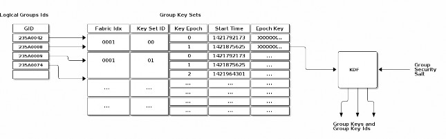
Figure 17. Group Key Derivation
Group Security Info
A hard-coded group security info is used to diversify the set of operational group keys. This value is hard-coded into the standard’s implementation, and thus is distributed with the associated code. Should the standard’s security mechanisms need to evolve (e.g. to upgrade encryption from AES- 128 to AES-256), the group security info can be changed to ensure that new keys will be derived for use in the new algorithm. The group security info SHALL be the byte stream "GroupKey v1.0", i.e.
0x47 0x72 0x6f 0x75 0x70 0x4b 0x65 0x79 0x20 0x76 0x31 0x2e 0x30.
With the exception of the group security info, all input key material SHALL be maintained on a per- Fabric basis.
Group Key Set
A group key set limits the key derivation process to Nodes within the respective operational groups. Access to a group key set is limited based on the functionality provided by a Node and/or the privilege afforded to it. For example, certain home security devices, such as a security system or door lock, may have access to a "Physical Access" group key set, while devices such as light bulbs or window coverings would not.
Operational group key lifetime is limited by assigning an expiration time to each epoch key in a given group key set. By constraining the validity of a given epoch key to an epoch, the ability for members to derive and operate with an operational group key can be constrained to particular periods of time. Epoch keys may be rotated on a periodic basis, and denying access to updated versions of these keys serves as a means to eject group members.
Epoch Keys
Epoch keys provide a means for limiting the lifetime of derived operational group keys. They also provide a way for an Administrator to revoke access to Nodes that have been explicitly excluded from an operational group (albeit after a period of time).

EpochKey = Crypto_DRBG(len = CRYPTO_SYMMETRIC_KEY_LENGTH_BITS)
Epoch keys are generated, managed, and stored by an Administrator on a per-Fabric basis. Each key SHALL be a random value of length CRYPTO_SYMMETRIC_KEY_LENGTH_BITS bits.
Each epoch key has associated with it a start time that denotes the time at which the key becomes active for use by transmitting Nodes. Epoch key start times are absolute UTC time in microseconds encoded using the epoch-us representation.
Using Epoch Keys
Nodes sending group messages SHALL use operational group keys that are derived from the current epoch key (specifically, the epoch key with the latest start time that is not in the future). Nodes that cannot reliably keep track of time calculate the current epoch key as described in Section 4.15.3.4, “Epoch Key Rotation without Time Synchronization”.
Nodes receiving group messages SHALL accept the use of any key derived from one of the currently installed epoch keys. This requirement holds regardless of whether the start time for the key is in the future or the past. This means Nodes continue to accept communication secured under an epoch key until that key is withdrawn by explicitly deleting the key from a Node’s group state by the key distribution Administrator.
Note that there is no end time associated with an epoch key. An epoch key marked with the maximum start time SHALL be disabled and render the corresponding epoch key slot unused.
Managing Epoch Keys
The epoch keys are managed using the Group Key Management Cluster. For every group key set published by the key distribution Administrator, there SHALL be at least 1 and at most 3 epoch keys in rotation. Key additions or updates are done using the KeySetWrite command.
Key updates are idempotent operations to ensure the Administrator is always the source of truth. An epoch key update SHALL order the keys from oldest to newest. For example, an update of the complete key set would look as follows:
a previous epoch key (EpochKey0)
a current epoch key (EpochKey1)
a new epoch key (EpochKey2).
Subsequent updates MAY deliver a partial key set but SHALL include EpochKey0 and MAY include EpochKey1 and EpochKey2. Any update of the key set, including a partial update, SHALL remove all previous keys in the set, however many were defined.
An Administrator MAY completely remove a group key set from a Node using the KeySetRemove command.
Epoch Key Rotation
The key distribution Administrator generates new epoch keys on a regular basis, giving each a unique id and adding them to the list of existing epoch keys within a group. The start time for each new epoch key is scheduled to occur after a configurable key propagation interval. The propagation interval is set sufficiently large such that the Administrator can synchronize all Nodes in the operational group with the new epoch key list within that time.
The rotation rate for epoch keys is expected to be on the order of days to weeks for typical applications, but the rate is configurable as required by the key distribution Administrator. Because of the relatively long rotation interval, and the overlap of active epoch keys, local clock drift within Nodes is generally not a concern.
Epoch Key Rotation without Time Synchronization
Although epoch keys are distributed with an associated start time, it is nonetheless possible for Nodes that do not maintain a synchronized clock to participate in key rotation. Specifically, upon receiving a new epoch key list from the key distribution Administrator, such a Node can note which of the keys is the current epoch key by comparing their relative start times (the current epoch key having the second newest time). It can then use the current key for all locally initiated security interactions until such time as it makes contact with the distribution Administrator again.
This scheme requires the Node to synchronize epoch keys with the key distribution Administrator at a rate that is at least as fast as the configured key propagation interval. The Administrator SHOULD provide three epoch keys to Nodes that do not maintain synchronized time (a previous epoch key, a current epoch key, and a new epoch key) so that they can maintain communication with other group members while a key update is in progress. The key distribution Administrator SHOULD update all Nodes without time, such as SEDs, before the new epoch key is activated, and
then let Nodes with time all roll to the new epoch key at the synchronized start time. Nodes that miss three or more epoch key updates are effectively removed from the group.
Epoch Key Rotation logic
The full life-cycle of Epoch Key rotation is shown in Figure 18, “Epoch Key Rotation”. For each epoch key slot, the start time of the key is shown as one of the following values:
New - a key with a start time in the future.
Current - the active key with the newest start time.
Previous - the active key with the second newest start time.
Old - an active key with the third or greater start time.
The diagram shows two types of state transitions:
Admin - an update of an old key by the Administrator. Changes made during this state transition are indicated in green.
Epoch Activate - activation of an epoch key due to system time becoming greater than the start time. Changes during this state transition are indicated in yellow.
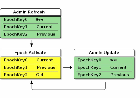
Figure 18. Epoch Key Rotation
The Admin Refresh state begins when an entire group key set is freshly written to a Node during commissioning or administration, such as when a new group is added. The Epoch Activate state is entered when time progresses to activate a fresh current epoch key, aging out the other epoch key slots. The Admin Update state is entered when an Administrator updates an old epoch key with a new epoch key. When in steady state, the Admin Refresh state MAY be entered in place of an Admin Update state transition to update additional keys to the required ones or to completely reset the group security.
Group Key Set ID
The Group Key Set ID is a 16-bit field that uniquely identifies the set of epoch keys used for derivation of an operational group key. Each Group Key Set ID is scoped to a particular Fabric and assigned by an Administrator so as to be unique within a Fabric.
The Group Key Set ID of 0 SHALL be reserved for managing the Identity Protection Key (IPK) on a given Fabric. It SHALL NOT be possible to remove the IPK Key Set if it exists.
Group Session ID

GroupKeyHash =
Crypto_KDF (
InputKey = OperationalGroupKey, Salt = [],
Info = "GroupKeyHash", Length = 16 // Bits
)
// GroupKeyHash is an array of 2 bytes (16 bits) per Crypto_KDF
// GroupSessionId is computed by considering the GroupKeyHash as a Big-Endian
// value. GroupSessionId is a scalar. Its use in fields within messages may cause a
// re-serialization into a different byte order than the one used for initial generation.
GroupSessionId = (GroupKeyHash[0] << 8) | (GroupKeyHash[1] << 0)
A Group Session ID is a special case of a 16-bit Session ID that is specifically used for group communication. When Session Type is 1, denoting a group session, the Session ID SHALL be a Group Session ID as defined here. The Group Session ID identifies probable operational group keys across a Fabric. The Group Session ID for a given operational group key is derived by treating the output of a Crypto_KDF against the associated Operational Group Key as a big-endian representation of a 16-bit integer, as follows:
where [] denotes a zero-length array. For example, given:
An Operational Group Key value of: a6:f5:30:6b:af:6d:05:0a:f2:3b:a4:bd:6b:9d:d9:60
After the above derivation following the definition of Crypto_KDF in Section 3.8, “Key Derivation Function (KDF)”, the resulting Group Session ID data would be:
Raw output of GroupKeyHash: b9:f7
Group Session ID scalar value to be used for further processing: 0xB9F7 (47607 decimal)
The Group Session ID MAY help receiving nodes efficiently locate the Operational Group Key used to encrypt an incoming groupcast message. It SHALL NOT be used as the sole means to locate the associated Operational Group Key, since it MAY collide within the fabric. Instead, the Group Session
ID provides receiving nodes a means to identify Operational Group Key candidates without the need to first attempt to decrypt groupcast messages using all available keys.
On receipt of a message of Group Session Type, all valid, installed, operational group key candidates referenced by the given Group Session ID SHALL be attempted until authentication is passed or there are no more operational group keys to try. This is done because the same Group Session ID might arise from different keys. The chance of a Group Session ID collision is 2-16 but the chance of both a Group Session ID collision and the message MIC matching two different operational group keys is 2-80.
Group Session Ids are sized to fit within the context of the Session Identifier field of a message. When used in this context, the Group Session ID value allows a receiving Node to identify the appropriate message encryption key to use from the set of active operational keys it has currently installed.
Distribution of Key Material
The operational group keys mechanism relies on a key distribution Administrator to reliably distribute select epoch key material to appropriate participants. It is assumed the key distribution Administrator is in possession of all epoch keys, has knowledge of the set of group security domain members which require access to those keys, and is responsible for pushing updates of these credentials to all authorized Nodes in those groups it manages.
Key material is distributed to key holders using the Group Key Management Cluster. In general, the key material of a Node is exposed via Attributes with ACL entries that only allow access by the key distribution Administrator. The information exposed in the Section 11.2, “Group Key Management Cluster” includes the group epoch keys and associated group session identifiers.
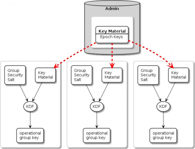
Figure 19. Group Key Distribution
Installing a Group onto a Newly Commissioned Node
This section provides an example of the operations required to install a group onto a newly commissioned node.
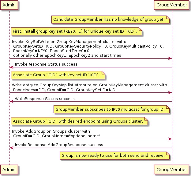
Figure 20. Installing a group onto a new node
Sequence:
Admin:
Generate fabric-unique group ID GID and random key key0 for group key set ID K.
Write the group key set K to the remote node, GroupMember, using KeySetWrite command.
Associate group ID GID with key set K by writing an entry to the GroupKeyMap list attribute.
GroupMember:
Node subscribes to the IPv6 multicast address generated from the fabric ID and group ID.
Admin:
Associate endpoint with group ID GID by sending the Groups cluster’s AddGroup command to endpoint.
Message Counter Synchronization Protocol (MCSP)
This section describes the protocol used to securely synchronize the message counter used by a sender of messages encrypted with a symmetric group key.
Message counter synchronization is an essential part of enabling secure messaging between members of an operational group. Specifically, it protects against replay attacks, where an attacker replays older messages, which may result in unexpected behaviour if accepted and processed by the receiver.
The recipient of a message encrypted with a group key can trust and process that message only if it has kept the last message counter received from a given sender using that key.
Underlying MCSP is a simple request / response protocol. When a multicast message with unknown counter is received, synchronization via MCSP begins by sending a synchronization request via unicast UDP to the multicast message originator’s unicast IPv6 address. That originator then sends a synchronization response to the unsynchronized node via unicast UDP. After cryptographic verification, the formerly unsynchronized node is now synchronized with the originator’s message counter and can trust the original and subsequent messages from the originator node.
Message Counter Synchronization Methods
There are two methods for synchronizing the message counter of a peer node, which are configurable per-group-key based on the GroupKeySecurityPolicy field of a given group key set (see GroupKeySetStruct).
Trust-first policy
The first authenticated message counter from an unsynchronized peer is trusted, and its message counter is used to configure message-counter-based replay protection on future messages from that node. All control messages (any message with C Flag set) use the control message counter and SHALL use Trust-first for synchronization. Note that MCSP is not used for Trust-first synchronization.
This policy provides lower latency for less security-sensitive applications such as lighting.

WARNING Trust-first synchronization is susceptible to accepting a replayed message after a Node has been rebooted.
Cache-and-sync policy
The message that triggers message counter synchronization is stored, a message counter synchronization exchange is initiated, and only when the synchronization is completed is the original message processed. Cache-and-sync provides replay protection even in the case where a Node has been rebooted, at the expense of higher latency.
Support for the cache-and-sync policy and MCSP is optional. A node indicates its ability to support this feature via the Group Key Management cluster FeatureMap.
Group Peer State
The Group Peer State Table stores information about every peer with which the node had a group message exchange. For every peer node id the following information is available in the table:
Peer’s Encrypted Group Data Message Counter Status:
Synchronized Data Message Counter - the largest encrypted data message counter received from the peer, if available.
Flag to indicate whether this counter value is valid and synchronized.
The message reception state bitmap tracking the recent window of data message counters received from the peer.
Peer’s Encrypted Group Control Message Counter Status:
Synchronized Control Message Counter - the largest encrypted control message counter received from the peer, if available.
Flag to indicate whether this counter value is valid and synchronized.
The message reception state bitmap tracking the recent window of control message counters received from the peer.
There are three scenarios where the receiver of an encrypted message does not know the sender’s last message counter:
The encrypted message is the first received from a peer.
The device rebooted without persisting the Group Peer State Table content. Note: it is not required to persist the Peer State Table.
The entry for the Peer in the Group Peer State Table was expunged due to the table being full.
The next sections describe the functional protocol used to request message counter synchronization with a peer and form responses to such message counter synchronization requests.
MCSP Messages
MsgCounterSyncReq - Message Counter Synchronization Request
The Message Counter Synchronization Request (MsgCounterSyncReq) message is sent when a message was received from a peer whose current message counter is unknown.
A MsgCounterSyncReq message SHALL set the C Flag in the message header. The control message counter SHALL be used for message protection.
A MsgCounterSyncReq message SHALL be secured with the group key for which counter synchronization is requested and SHALL set the Session Type to 1, indicating a group session as per the rules outline in Section 4.16.5, “Message Counter Synchronization Exchange”.
The payload of the MsgCounterSyncReq message takes the format defined in Table 24, “Message Counter Sync Request”:
Table 24. Message Counter Sync Request
Field Size
Message Field
Description
8 bytes
Challenge
The Challenge is a 64-bit random number generated using the DRBG by the initiator of a MsgCounterSyncReq to uniquely identify the synchronization request cryptographically.
MsgCounterSyncRsp - Message Counter Synchronization Response
The Message Counter Synchronization Response (MsgCounterSyncRsp) message is sent in response to a MsgCounterSyncReq.
A MsgCounterSyncRsp message SHALL set the C Flag in the message header. The control message counter SHALL be used for message protection.
The MsgCounterSyncRsp message has the format defined in Table 25, “Message Counter Sync Response”:
Table 25. Message Counter Sync Response
Field Size
Message Field
Description
4 bytes
Synchronized Counter
The current data message counter for the node sending the MsgCounterSyncRsp message.
8 bytes
Response
The Response SHALL be the same as the 64-bit value sent in the Challenge field of the corresponding MsgCounterSyncReq.
Unsynchronized Message Processing
An unsynchronized message is one that is cryptographically verified from a node whose message counter is unknown. Upon receipt of an unsynchronized message process the message as follows:
The message SHALL be of Group Session Type, otherwise discard the message.
If C Flag is set to 1:
Create a Message Reception State and set its max_message_counter to the message counter of the given message, i.e. trust-first.
Accept the message for further processing.
If C Flag is set to 0:
Determine the Section 11.2.6.2.2, “GroupKeySecurityPolicy” (as set by the Section 11.2, “Group Key Management Cluster”) of the operational group key used to authenticate the message.
If the key has a trust-first security policy, the receiver SHALL:
Set the peer’s group key data message counter to Message Counter of the message.
Clear the Message Reception State bitmap for the group session from the peer.
Mark the peer 's group key data message counter as synchronized.
Process the message.
If the key has a cache-and-sync security policy, the receiver SHALL:
If MCSP is not in progress for the given peer Node ID and group key:
Store the message for later processing.
Proceed to Section 4.16.5, “Message Counter Synchronization Exchange”.
Otherwise, do not process the message.
An implementation MAY queue the message for later processing after MCSP completes if resources allow.
For each peer Node ID and group key pair there SHALL be at most one synchronization exchange outstanding at a time.
Message Counter Synchronization Exchange
A message synchronization exchange starts by sending the MsgCounterSyncReq message to the peer Node that sent the message with unknown message counter. When a synchronization request is triggered by an incoming multicast message, the Node SHALL first wait for a uniformly random amount of time between 0 and MSG_COUNTER_SYNC_REQ_JITTER.
The sender of the MsgCounterSyncReq message SHALL:
Set the Message Header fields as follows:
The S Flag SHALL be set to 1.
The DSIZ field SHALL be set to 1.
The P Flag SHALL be set to 1.
The C Flag SHALL be set to 1.
The Session Type field SHALL be set to 1.
The Session ID field SHALL be set to the Group Session Id for the operational group key being synchronized.
The Source Node ID field SHALL be set to the Node ID of the sender Node.
The Destination Node ID field SHALL be set to the Source Node ID of the message that triggered the synchronization attempt.
Create a new synchronization Exchange.
The Exchange ID of the message SHALL be set to match the new Exchange.
The I Flag SHALL be set to 1.
The A Flag SHALL be set to 0.
The R Flag SHALL be set to 1.
Set the Challenge field to the value returned by Crypto_DRBG(len = 8 * 8) and store that value to resolve synchronization responses from the destination peer.
Arm a timer to enforce that a synchronization response is received before MSG_COUNTER_SYNC_TIMEOUT.
Upon firing of the timer:
The synchronization exchange SHALL be closed.
Any message waiting on synchronization associated with the exchange SHALL be discarded.
The timer SHALL be stopped upon receipt of an authenticated MsgCounterSyncRsp message that matches:
The Source Node ID field matches the Destination Node ID field of the most recent
MsgCounterSyncReq message generated for that Node.
The Response field corresponds to the Challenge field of the MsgCounterSyncReq
message.
Invoke Section 4.6.1, “Message Transmission” using parameters from step 1 to encrypt and then send the request message over UDP to the IPv6 unicast address of the destination.
The request message SHALL use the same operational group key as the message which triggered synchronization.
The group key SHALL be known/derivable by both parties (sender and receiver).
The receiver of MsgCounterSyncReq SHALL:
Verify the Destination Node ID field SHALL match the Node ID of the receiver, otherwise discard the message.
Respond with MsgCounterSyncRsp.
The sender of the MsgCounterSyncRsp response message SHALL:
Set the Message Header fields as follows:
The S Flag SHALL be set to 1.
The DSIZ field SHALL be set to 1.
The P Flag SHALL be set to 1.
The C Flag SHALL be set to 1.
The Session Type field SHALL be set to 1.
The Session ID field SHALL be set to the Group Session Id for the operational group key being synchronized.
The Source Node ID field SHALL be set to the Node ID of the sender Node.
The Destination Node ID field SHALL be set to the Source Node ID of the
MsgCounterSyncReq.
Set the MsgCounterSyncRsp payload fields as follows:
The Response field SHALL be set to the value of the Challenge field from the
MsgCounterSyncReq.
The Synchronized Counter field SHALL be set to the current Global Group Encrypted Data
Message Counter of the sender.
Use the same exchange context as the MsgCounterSyncReq being responded to.
The Exchange ID of the message SHALL be set to the Exchange ID of the MsgCounterSyncReq.
The I Flag SHALL be set to 0.
The A Flag SHALL be set to 1.
The R Flag SHALL be set to 1.
Invoke Section 4.6.1, “Message Transmission” using parameters from step 1 to encrypt and then send the response message over UDP to the IPv6 unicast address of the destination.
The receiver of the MsgCounterSyncRsp message SHALL:
Verify the MsgCounterSyncRsp matches a previously sent MsgCounterSyncReq:
An active synchronization exchange SHALL exist with the source node.
The Exchange ID field SHALL match the Exchange ID used for the original
MsgCounterSyncReq message.
The Response field SHALL match the Challenge field used for the original
MsgCounterSyncReq message.
The Destination Node ID field SHALL match the Source Node ID of the original
MsgCounterSyncReq message.
The Source Node ID field SHALL match the Destination Node ID of the original
MsgCounterSyncReq message.
On verification failure:
Silently ignore the MsgCounterSyncRsp message.
On verification success:
Set the peer’s group key data message counter to Synchronized Counter.
Clear the Section 4.5.4.1, “Message Reception State” bitmap for the peer.
Mark the peer 's group key data message counter as synchronized.
Resume processing of any queued message that triggered synchronization according to Section 4.5.6, “Counter Processing of Incoming Messages”.
If more than one message is queued from the synchronized peer, using the same operational group key, the messages SHALL be processed in the order received.
Close the synchronization exchange created for the original MsgCounterSyncReq message.
Message Counter Synchronization Session Context
While conducting Message Counter Synchronization with a peer, nodes SHALL maintain the following session context. For nodes initiating message counter synchronization, this context SHALL be maintained throughout the full exchange of MsgCounterSyncReq and MsgCounterSyncRsp messages. For nodes responding to MsgCounterSyncReq messages, the context SHALL only be maintained long enough to generate and successfully transmit the MsgCounterSyncRsp message.
Fabric Index: Records the Index for the Fabric within which nodes are conducting message counter synchronization.
Fabric Index is derived by identification of an Operational Group Key associated with the fabric through successful decryption with that key and verification of the Message Integrity Check. For nodes initiating counter synchronization, this occurs at decryption of an inbound groupcast message. For nodes in the responder role, this occurs at decryption of an inbound MsgCounterSyncReq message.
Peer Node ID: Records the node ID of the peer with which message counter synchronization is being conducted.
For nodes initiating message counter synchronization, this is the node ID of the responder. For nodes responding to message counter synchronization, this is the node ID of the initiator.
Role: Records whether the node is the initiator of or responder to message counter synchronization.
Together, Fabric Index, Peer Node ID and Role comprise a unique key that can be used to match incoming messages to ongoing MCSP exchanges.
Message Reception State: Provides tracking for the Control Message Counter of the remote peer.
Peer IP Address: The unicast IP address of the peer.
Peer Port: The receiving port of the peer.
Operational Group Key: The Operational Group Key that is being used to encrypt messages within the counter synchronization exchange.
Group Session ID: Records the Group Session ID derived from the Operational Group Key that is being used to encrypt messages within the counter synchronization exchange.
Sequence Diagram
The following sequence diagram shows an example of how message counter synchronization behaves in the most common scenario.
Scenario 1 — Multicast Receiver Initiated
Assumptions:
Sender transmits a multicast message.
Receiver does not know Sender 's message counter.
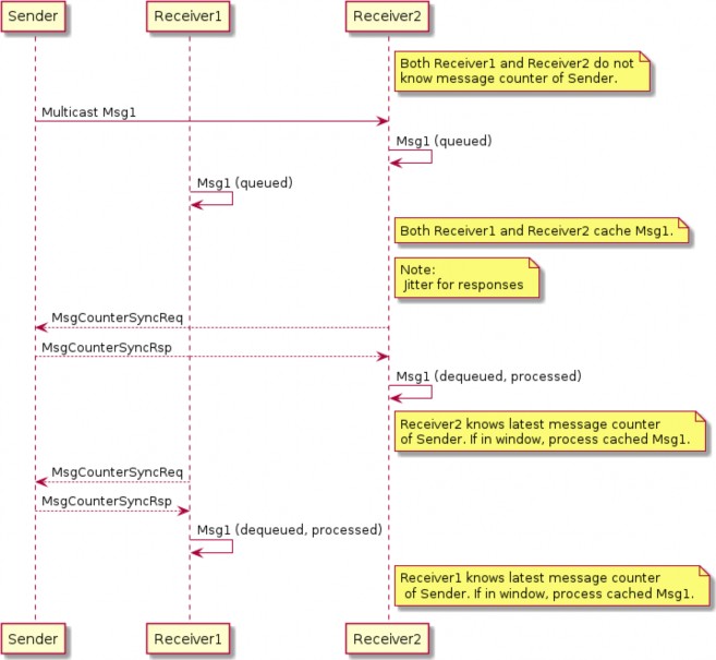
Figure 21. Multicast Receiver Initiated Message Counter Synchronization
Sequence:
Sender:
Generates, encrypts and sends Msg1 as a multicast message. Msg1 could be:
Regular message that starts encrypted group communication with receivers Receiver1
and Receiver2.
Receivers Receiver1 and Receiver2 each:
Receive, decrypt, authenticate, and cache Msg1 message for later processing.
Generate, encrypt, and send MsgCounterSyncReq message.
Sender:
Receives MsgCounterSyncReq message.
Generates, encrypts and sends MsgCounterSyncRsp message.
R1 and R2 each:
Receive, decrypt, process, and verify MsgCounterSyncRsp message from Sender.
On verification success: marks Sender 's group key message counter as synchronized.
Processes cached Msg1 message.
Bluetooth Transport Protocol (BTP)
The Bluetooth Transport Protocol (BTP) provides a TCP-like layer of reliable, connection-oriented data transfer on top of GATT. BTP splits individual Service Data Unit (SDU) messages into multiple BTP segments, which are each transmitted via a single GATT write or indication (as shown in Figure 22, “MATTERoBLE: Matter Message / BTP layering”).
While BTP is a generic protocol, Matter specifically uses BTP to define a Matter-over-Bluetooth Low Energy (MATTERoBLE) Interface. A MATTERoBLE Interface MUST implement BTP as a universally compatible transport mode. A MATTERoBLE Interface SHALL only be used to transport Matter messages as the BTP SDU.
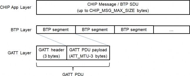
Figure 22. MATTERoBLE: Matter Message / BTP layering
The BTP session handshake allows devices to check BTP protocol version compatibility and exchange other data before a BTP session is established. Once established, this session is used to send and receive BTP SDUs (such as Matter messages) as BTP Message Segments. A BTP session MAY open and close with no effect on the state of the underlying Bluetooth LE connection, except in the case where a BTP session is closed by the Peripheral Device. Either the Peripheral or the Central MAY signal the end of a BTP session by closing the underlying BLE connection.
Due chiefly to constraints put on design by resource-limited BLE chipsets, BTP defines a receive window for each side of a session in units of GATT PDUs. Each GATT Write Characteristic Value (ATT_WRITE_REQ) PDU or Indication (ATT_HANDLE_VALUE_IND) PDU is sent with a sequence number which the receiver uses to acknowledge receipt of each packet at the BTP layer and open its receive window from the sender’s perspective.
BTP Session Interface
Conceptually, an open BTP session is exposed to the next-higher session layer as a full-duplex
message stream.
BTP Frame Formats
A BTP Frame consists of an 8-bit header followed by one or more optional fields, as detailed below. BTP uses little endian encoding for any header fields larger than one byte in length.
BTP Packet Protocol Data Unit
Table 26, “BTP Packet PDU format” defines the BTP Packet PDU format. Unused fields SHALL be set to '0'.
Table 26. BTP Packet PDU format
bit 0
1
2
3
4
5
6
7
8
9
10
11
12
13
14
15
-
H
M
-
A
E
-
B
[Management Opcode]
[Ack Number]
[Sequence Number]
[Message Length]
[Segment Payload]…
…
H (Handshake) bit
Set to '0' for normal BTP packets. When set, this bit indicates a BTP handshake packet for session establishment and has a different packet format described below.
M (Management Message) bit
Indicates the presence ('1') or absence ('0') of the Management Opcode field. All segments of a message MUST set this bit to the same value.
A (Acknowledgement) bit
Indicates the presence of the Ack Number field.
B (Beginning Segment) bit
Set to '1' on the first segment of a BTP SDU and set to '0' for all remaining segments of the same BTP SDU. It indicates the presence of the Message Length field.
E (Ending Segment) bit
Set to '1' on the last segment of a BTP SDU and set to '0' for all other segments of the same BTP SDU. A segment MAY have both the Beginning and Ending bits set indicating that a full BTP SDU is included in the message. When set, the segment payload length is equal to the total remaining unreceived message data. When not set, the segment payload length is equal to the maximum allowable BTP session packet size minus header overhead.
Ack Number
Optional field specified in Section 4.17.3.8, “Packet Acknowledgements”.
Sequence Number
Mandatory field for regular data messages specified in Section 4.17.3.6, “Sequence Numbers”.
Message Length
Optional field present in Beginning Segment only. Value indicates the length in bytes of the full message buffer to be transmitted. None of the BTP Packet PDU fields is included in the Message Length.
Segment Payload
Optional field containing a segment of the Service Data Unit (SDU) message in transmission to the receiver.
BTP Control Frames
BTP defines different control frame formats depending on the Management Opcode that is in the BTP Packet PDU header. Valid Management Opcodes for BTP Control Frames are defined in Table 27, “BTP Control codes”.
Table 27. BTP Control codes
Management Opcode
Name
Description
0x6C
Handshake
Request and response for BTP session establishment
BTP Handshake Request
Table 28. BTP Handshake Request format
bit 0
1
2
3
4
5
6
7
8
9
10
11
12
13
14
15
0
H=1
M=1
0
A=0
E=1
0
B=1
Management Opcode = 0x6C
Ver[1]
Ver[0]
Ver[3]
Ver[2]
Ver[5]
Ver[4]
Ver[7]
Ver[6]
BTP Segment Size
Client Window Size
H (Handshake) bit
Set to '1' for connection handshake messages.
M (Management) bit
Set to '1' for connection handshake messages.
Ver[i] (Version) nibbles
Used to negotiate the highest version capability between a Device pair. Supported versions are listed once each, newest first, in descending order. Unused version fields are filled with ‘0’.
The following values are defined:
0 — Unused field
4 — BTP as defined by Matter v1.0
BTP Segment Size
BTP Segment size is a 16-bit unsigned integer field containing the size of the GATT PDU (ATT_MTU) that can be received by the sender minus the size of the GATT header (3). This value is obtained via the standard ATT MTU exchange procedure (see Bluetooth® Core Specification 4.2 Vol 3, Part F, Section 3.4.2 "MTU Exchange") and is used to validate that both sides of the BLE connection are using the common minimum value. If BTP is not aware of the negotiated GATT MTU, the value shall be set to '20', indicating the minimum ATT_MTU(23) defined by GATT minus 3.
Note that each GATT PDU used by the BTP protocol introduces 3 byte header overhead making maximum size of the BTP payload equal to negotiated ATT_MTU-3.
Client Window Size
Value of the maximum receive window size supported by the server, specified in units of BTP packets where each packet may be up to 244 bytes in length. This maximum was chosen so a single BTP segment can fit into a single 255 byte BLE link layer PDU, including all headers from the link layer, L2CAP, GATT, and BTP.
BTP Handshake Response
Table 29. BTP Handshake Response format
bit 0
1
2
3
4
5
6
7
8
9
10
11
12
13
14
15
0
H=1
M=1
0
A=0
E=1
0
B=1
Management Opcode = 0x6C
Reserved
Final Protocol Version
Selected BTP Segment Size (low byte)…
…Selected BTP Segment Size (high byte)
Selected Window Size
H (Handshake) bit
Set to '1' for session handshake messages.
M (Management) bit
Set to '1' for session handshake messages.
Reserved
Must be set to '0'.
Final Protocol Version
Value of the BTP protocol version selected by the server.
Selected BTP Segment Size
Value of the maximum BTP segment size for the connection selected by the server as a 16-bit unsigned integer.
Selected Window Size
Value of the maximum receive window size supported by the server, specified in units of BTP packets where each packet may be up to the selected segment size in length.
BTP GATT Service
BTP Channelization
Bluetooth Transport Protocol provides a packetized stream interface over GATT but says nothing about the actual contents of the data packets it transports. The BTP Service UUID is used to specify the actual contents of the packets (see Table 30, “BTP Service UUID”).
Table 30. BTP Service UUID
BTP Datagram Contents
BTP Service UUID
Matter Message frames
MATTER_BLE_SERVICE_UUID
Note: See Section 4.17.5, “Bluetooth SIG Considerations” for terms of use.
While a single BTP connection may exist between a BTP Client and BTP Server, multiple BTP sessions may be established between various peers.
BTP GATT Service
The BTP GATT service is composed of a service with three characteristics—C1, C2 and C3 (see Table 31, “BTP GATT service”). The client SHALL exclusively use C1 to initiate BTP sessions by sending BTP handshake requests and send data to the server via GATT ATT_WRITE_CMD PDUs. While a client is subscribed to allow indications over C2, the server SHALL exclusively use C2 to respond to BTP handshake requests and send data to the client via GATT ATT_HANDLE_VALUE_IND PDUs.
Table 31. BTP GATT service
Attribute
Description
BTP Service
UUID = MATTER_BLE_SERVICE_UUID
C1 Characteristic (Client TX Buffer)
UUID = 18EE2EF5-263D-4559-959F-4F9C429F9D11
Characteristic Porperties = Write max length = 247 bytes
Attribute
Description
C2 Characteristic (Client RX Buffer)
UUID = 18EE2EF5-263D-4559-959F-4F9C429F9D12
Characteristic Properties = Indication max length = 247 bytes
C3 Characteristic
(Additional commissioning- related data)
UUID = 64630238-8772-45F2-B87D-748A83218F04
Characteristic Properties = Read max length = 512 bytes
For all messages sent from the BTP Client to BTP Server, BTP SHALL use the GATT Write Characteristic Value sub-procedure. For all messages sent from the BTP Server to BTP Client, BTP SHALL use the GATT Indications sub-procedure.
The values of C1 and C2 SHALL both be limited to a maximum length of 247 bytes. This constraint is imposed to align with maximum PDU size when LE Data Packet Length Extensions (DPLE) is enabled on Bluetooth 4.2 hardware. Per Bluetooth® Core Specification 4.2 Vol 3, Part F, Section 3.2.9 "Long Attribute Values", the maximum characteristic value length is 512 bytes. The maximum lengths of C1 and C2 may increase in a future version of the BTP specification to allow higher throughput on BLE connections whose ATT_MTU exceeds 247 bytes.
C3 is an optional characteristic that the server MAY use to include additional data required during the provisioning as defined in Section 5.4.2.5.7, “GATT-based Additional Data”.
BTP Clients SHALL perform certain GATT operations synchronously, including GATT discovery, subscribe, and unsubscribe operations. GATT discovery, subscribe, or unsubscribe SHALL NOT be initiated while the result of a previous operation remains outstanding. This requirement is imposed by GATT protocol.
Session Establishment
Before a BTP session can be initiated, a central SHALL first establish a BLE connection to a peripheral. Once a BLE connection has been formed, centrals SHALL assume the GATT client role for BTP session establishment and data transfer, and peripherals SHALL assume the GATT server role. If peripheral supports LE Data Packet Length Extension (DPLE) feature it SHOULD perform data length update procedure before establishing a GATT connection.
Before establishing a BTP session, the GATT client SHOULD perform a GATT Exchange MTU procedure.
After that the BTP Client SHALL execute the GATT discovery procedure. The GATT discovery procedure starts with primary service discovery using either the GATT Discover All Primary Services sub-procedure or the GATT Discover Primary Services by Service UUID sub-procedure.
The BTP Client SHALL perform either the GATT Discover All Characteristics of a Service sub- procedure or the GATT Discover Characteristics by UUID sub-procedure in order to discover the C1 and C2 characteristics.
The BTP Client SHALL perform the GATT Discover All Characteristic Descriptors sub-procedure in
order to discover the Client Characteristic Configuration descriptor (CCCD) of C2 characteristic.
To initiate a BTP session, a BTP Client SHALL send a BTP handshake request packet to the BTP Server via a ATT_WRITE_CMD PDU on characteristic C1 of the BTP Service. The handshake request packet SHALL include, a list of BTP protocol versions supported by the client, the client’s GATT ATT_MTU, and the client’s maximum receive window size. The list of supported protocol versions SHALL be sorted in descending numerical order. If the client cannot determine the BLE connection’s ATT_MTU, it SHALL specify a value of '23' (the minimum ATT_MTU supported by GATT) for this field in the handshake request. For a detailed specification of the handshake request binary data format, see Section 4.17.2.3, “BTP Handshake Request”.
After the BTP Client acknowledges delivery of the handshake request packet, upon receipt of a GATT Write Response, the BTP Client SHALL enable indications over C2 characteristics by writing value 0x01 to C2’s Client Characteristic Configuration descriptor as described in Bluetooth® Core Specification 4.2 Vol 3, Part C, Section 10.3.1.1 "Handling GATT Indications and Notifications".
Once the GATT server has received a client’s BTP handshake request and confirmed the client’s subscription to C2, it SHALL send a BTP handshake response to the client via a ATT_HANDLE_VALUE_IND PDU on C2. This response SHALL contain the window size, maximum BTP packet size, and BTP protocol version selected by the server. For a detailed specification of the handshake response binary data format, see Section 4.17.2.4, “BTP Handshake Response”.
The server SHALL select a window size equal to the minimum of its and the client’s maximum window sizes. Likewise, the server SHALL select a maximum BTP session packet size for the BLE connection by taking the minimum of 244 bytes (the maximum characteristic value length of C1 and C2), server’s ATT_MTU-3 and ATT_MTU-3 as declared by the client.
The server SHALL select a BTP protocol version that is the newest which it and the client both support, where newer protocol version numbers are strictly larger than those of older versions. The version number returned in the handshake response SHALL determine the version of the BTP protocol used by client and server for the duration of the session.
If the server determines that it and the client do not share a supported BTP protocol version, the server SHALL close its BLE connection to the client. When a client sends a handshake request, it SHALL start a timer with a globally-defined duration of BTP_CONN_RSP_TIMEOUT seconds. If this timer expires before the client receives a handshake response from the server, the client SHALL close the BTP session and report an error to the application. Likewise, a server SHALL start a timer with the same duration when it receives a handshake request from a client. If this timer expires before the server receives a subscription request on C2, the server SHALL close the BTP session and report an error to the application. The state machine in Figure 23, “BTP session handshake” illustrates the function of these timers as part of the BTP session establishment procedure.
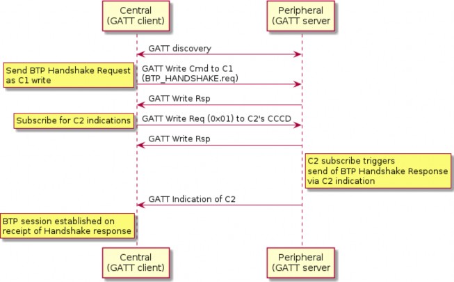
Figure 23. BTP session handshake
Data Transmission
Once a BTP session has been established, the next-higher-layer application on both peers may use this BLE connection to send and receive data via GATT writes or indications, according to a peer’s GATT role. Clients SHALL exclusively use GATT Write Characteristic Value sub-procedure to send data to servers and servers SHALL exclusively use GATT Indication sub-procedure to send data to clients.
All BTP packets sent on an open BLE connection SHALL adhere to the BTP Packet PDU binary data format specified in BTP Frame Formats. All BTP packets SHALL include a header flags byte and an 8-bit unsigned sequence number. All other packet fields are optional. These optional fields include an 8-bit unsigned received packet acknowledgement number, 16-bit unsigned buffer length indication, and variable-length buffer segment payload.
This section is defined entirely within the scope of a single BTP session. Concurrent BTP sessions between the same peer and multiple remote hosts SHALL maintain separate and independent acknowledgement timers, sequence numbers, and receive windows.
Message Segmentation and Reassembly
When the session layer (that is, MATTERoBLE) sends a Matter Message as a BTP SDU over a BTP session, that BTP SDU SHALL be split into ordered, non-overlapping BTP segments so the set of all BTP segments may be reassembled into the original BTP SDU (see Figure 22, “MATTERoBLE: Matter Message / BTP layering”). Each BTP segment SHALL be prepended with a BTP packet header and sent as the payload of a single GATT PDU. If a BTP SDU is split into more than one BTP segment, the BTP segments SHALL be sent in order of their position in the original BTP SDU, starting with the BTP segment at the buffer’s head.
At any point in time, only one BTP SDU may be transmitted in each direction over a BTP session. The transmission of BTP segments of any two BTP SDUs SHALL not overlap. If the application attempts to send one BTP SDU while transmission of another BTP SDU is in progress, the new BTP SDU SHALL be appended to a first-in, first-out queue. The next BTP SDU SHALL be dequeued from this queue and transmitted once transmission of the current BTP SDU completes, that is, once all BTP segments of the current BDP SDU have been transmitted and received by the peer via GATT.
The first BTP segment of a BTP SDU sent over a BTP session SHALL have its Beginning Segment header flag set to indicate the beginning of a new BTP SDU (see Table 26, “BTP Packet PDU format”). The presence of this flag SHALL indicate the further presence of a 16-bit unsigned integer field, the Message Length, that provides the receiver with the total length of the BTP SDU. The last BTP segment for a given BTP SDU SHALL have its Ending Segment flag set to indicate the end of the transmitted BTP SDU. A BTP packet that bears an unsegmented BTP SDU—that is, a BTP SDU small enough to fit into a single BTP segment—SHALL have both its Beginning Segment and Ending Segment flags set.
The size of a single BTP SDU sent via BTP is limited to 64KB, that is, the maximum size of the Message Length field in the BTP packet header. The number of segments used to send a buffer is unlimited and delimited by the Beginning Segment and Ending Segment bits in the BTP packet header. The upper layer imposes more stringent requirements over the maximum SDU size, such as Section 4.4.4, “Message Size Requirements”.
The length of the data payload in each BTP segment whose Ending Segment bit is not set SHALL be equal to the session’s maximum BTP packet size minus the size of that packet’s header. If a packet’s Ending Segment bit is set, the length of its BTP segment data payload SHALL equal the size of the original BTP SDU minus the total size of all previously transmitted BTP segments of that BTP SDU. In this way, the length of a SDU’s last BTP segment is implied by its size.
Once a peer receives a complete set of BTP segments, it SHALL reassemble them in the order received, and verify that the reassembled BTP SDU’s total length matches that specified by the Beginning Segment’s Message Length value. If they match, the receiver SHALL pass the reassembled BTP SDU up to the next-higher-layer. If the reassembled buffer’s length does not match that specified by the sender, or if received BTP segment payload size would exceed the maximum BTP packet size, or receiver receives an Ending Segment without the presence of a previous Beginning Segment, or a Beginning Segment when another BTP SDU’s transmission is already in progress, the receiver BTP SHALL close the BTP session and report an error to the application.
Sequence Numbers
All BTP packets SHALL be sent with sequence numbers, regardless of whether they contain SDU segments (for example, a packet acknowledgement with no attached segment payload). The purpose of sequence numbers is to facilitate the BTP receive window. A BTP sequence number SHALL be defined as an unsigned 8-bit integer value that monotonically increments by 1 with each packet sent by a given peer. A sequence number incremented past 255 SHALL wrap to zero.
Sequence numbers SHALL be separately defined for either direction of a BTP session. The sequence number of the first packet sent by the client after completion of the BTP session handshake SHALL be zero. The server’s BTP handshake response bears an implied sequence number of zero because it occupies a slot in the client’s receive window. The client acknowledges the server’s BTP
handshake response with an acknowledgement sequence of zero. For this reason, the sequence number of the first data packet sent by the server after completion of the BTP session handshake SHALL be 1.
Peers SHALL check to ensure that all received BTP packets properly increment the sender’s previous sequence number by 1. If this check fails, the peer SHALL close the BTP session and report an error to the application.
Receive Windows
The purpose of the receive window is to enable flow control at the GATT session layer between BTP peers.
Flow control is required at the GATT transport layer for embedded platforms that use "minimal" BLE chipsets. These platforms may have limited space on the host processor to receive packets from their BLE chipsets. In the case of some dual-chip architectures, writes and indications are received and confirmed by the BLE chip with no input from the host processor. When the BLE chip sends the result of a received GATT PDU to the host processor, that payload and the corresponding BTP packet will be permanently lost if the host does not have enough space to receive it. For this reason, knowledge of a remote host’s ability to reliably receive GATT PDUs is presented at the transport layer in the form of the BTP receive window.
Both peers in a BTP session SHALL define a receive window, where the window’s size indicates the number of GATT PDUs (that is, BTP segments) a peer can reliably receive and store without session- layer acknowledgment. A maximum window size SHALL be established for both peers as part of the BTP session handshake. To prevent sequence number wrap-around, the largest maximum window size any peer may support is 255.
Both peers SHALL maintain a counter to reflect the current size of the remote peer’s receive window. Each peer SHALL decrement this counter when it sends a packet via GATT write or indication and increment this counter when a sent packet is acknowledged.
If a local peer’s counter for a remote peer’s receive window is zero, the window SHALL be considered closed, and the local peer SHALL NOT send packets until the window reopens (is incremented above zero). When a closed window reopens, a local peer SHALL immediately resume any pending BTP packet transmission.
A local peer SHALL also not send packets if the remote peer’s receive window has one slot open and the local peer does not have a pending packet acknowledgement. This is to avoid the situation where the receive windows of both peers are full and neither can send an acknowledgement to reopen its window for the other. Because the server’s handshake response bears an implicit BTP sequence number of zero, a server SHALL initialize its counter for the client’s receive window size at (negotiated maximum window size - 1). A client SHALL initialize its counter for the server’s receive window at the negotiated maximum window size.
Both peers SHALL also keep a counter of their own receive window size based on the sequence number difference between the last packet they received and the last packet they acknowledged. This counter is used to proactively send early packet acknowledgements when a peer’s own receive window is about to close. See Section 4.17.3.8, “Packet Acknowledgements” for details.
An example scenario involving BTP receive windows is depicted in Figure 24, “Example receive window scenario”, complete with packet acknowledgements as specified in Section 4.17.3.8, “Packet Acknowledgements”. In this scenario, the client transmits a three-segment buffer to the server once it receives the server’s handshake request. The handshake request occupies one slot in the client’s initial receive window. The server’s initial receive window is empty. Both client and server have a maximum window size of 4.
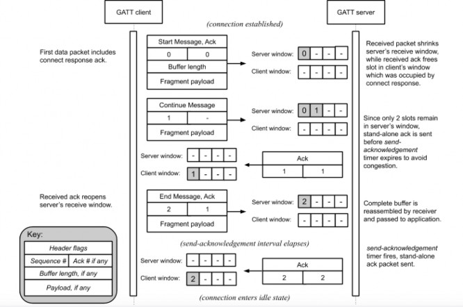
Figure 24. Example receive window scenario
Packet Acknowledgements
The purpose of sequence numbers and packet receipt acknowledgements is to support the BTP receive window and provide a keep-alive signal when a session is idle to affirm the health and continued operation of a remote BTP stack.
Per BTP Frame Formats, BTP packet receipt acknowledgements SHALL be received as unsigned 8- bit integer values in the header of a BTP packet. The value of this field SHALL indicate the sequence number of the acknowledged packet.
Acknowledgement of a sequence number indicates acknowledgement of the previous sequence number, if it too is unacknowledged. By induction, acknowledgement of a given packet implies acknowledgement of all packets received on the same BTP session prior to the acknowledged packet.
An acknowledgement is invalid if the acknowledged sequence number does not correspond to an outstanding, unacknowledged BTP packet sequence number. In contrast to TCP, BTP acks are not "free." A stand-alone ack—that is, a BTP packet that contains a packet receipt acknowledgement
value but no buffer segment payload—consumes a slot in a remote peer’s window just like any other packet. Stand-alone acknowledgement packets SHALL be acknowledged by a remote peer. The implications of this are examined in Section 4.17.3.9, “Idle Connection State”.
Each peer SHALL maintain an acknowledgement-received timer. When a peer sends any BTP packet, it SHALL start this timer if it is not already running. The timer’s duration SHALL be globally defined as BTP_ACK_TIMEOUT seconds, referred to as the acknowledgement timeout interval.
A peer SHALL restart its acknowledgement-received timer when a valid acknowledgement is received for any but its most recently sent unacknowledged packet. A peer SHALL stop its acknowledgement-received timer if it receives an acknowledgement for its most recently sent unacknowledged packet. If a peer’s acknowledgement-received timer expires, or if a peer receives an invalid acknowledgement, the peer SHALL close the BTP session and report an error to the application.
Because the server’s handshake response bears an implicit BTP sequence number of zero, a server SHALL start its acknowledgement-received timer when it sends a handshake response.
Each peer SHALL also maintain a send-acknowledgement timer. When it receives any BTP packet, a peer SHALL record the packet’s sequence number as the corresponding BTP session’s pending acknowledgement value and start the send-acknowledgement timer if it is not already running. The timer’s duration timer SHALL be defined as any value less than one-half the acknowledgement timeout interval. This ensures that on a healthy BLE connection, a peer will always receive acknowledgements for sent packets before its acknowledgement-received timer expires.
A peer SHALL stop its send-acknowledgement timer when any pending acknowledgement is sent, either as a stand-alone BTP packet or piggybacked onto an outgoing buffer segment. If this timer expires and the peer has a pending acknowledgement, the peer SHALL immediately send that acknowledgement. If the peer sends any packet before this timer expires, it SHALL piggyback any pending acknowledgement on the transmitted packet and stop the send-acknowledgement timer.
Because the server’s handshake response bears an implicit BTP sequence number of zero, a client SHALL set its pending acknowledgement value to zero and start its send-acknowledgement timer when it receives the server’s a handshake response. Operation of the send-acknowledgement and acknowledgement-received timers is illustrated in Figure 26, “BTP session lifecycle for Central acting as GATT Client” in Section 4.17.3.11, “Protocol State Diagrams”.
If a peer detects that its receive window has shrunk to two or fewer free slots, it SHALL immediately send any pending acknowledgement as a stand-alone BTP packet. This prevents the session from stalling in the interval between when a peer’s receive window becomes empty and when its send-acknowledgement timer would normally fire.
Idle Connection State
When neither side of a BTP session has data to send, BTP packets will still be exchanged every send- acknowledgement interval due to acknowledgements generated by the receipt of previous data or stand-alone acknowledgement packets, as discussed in Section 4.17.3.8, “Packet Acknowledgements”. The behavior of the acknowledgement-received timer in this scenario doubles as a keep-alive mechanism, as it will cause a peer to close a BLE connection automatically if the remote BTP stack crashes or becomes unresponsive. This scenario is illustrated in Figure 25, “Idle
connection scenario”.
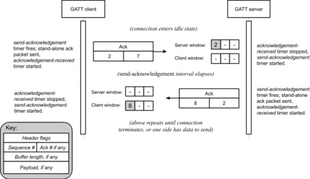
Figure 25. Idle connection scenario
Connection Shutdown
To close a BTP session, a GATT client SHALL unsubscribe from characteristic C2. The GATT server SHALL take this action to indicate closure of any BTP session open to the client.
If a BTP Server needs to close the BTP session, it SHALL terminate its BLE connection to the client.
Protocol State Diagrams
Figure 26, “BTP session lifecycle for Central acting as GATT Client” shows the state machine for BTP session management of a BTP Client Device.
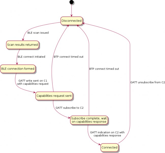
Figure 26. BTP session lifecycle for Central acting as GATT Client
Figure 27, “BTP session lifecycle for Peripheral acting as GATT Server” shows the state machine for BTP session management of a BTP Server Device.
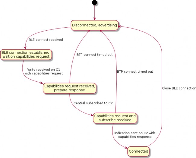
Figure 27. BTP session lifecycle for Peripheral acting as GATT Server
Note that in Figure 27, “BTP session lifecycle for Peripheral acting as GATT Server”, the state machine is identical for GATT clients and servers with the distinction that clients send data to servers via confirmed writes, and servers send data to clients via indications.
Figure 28, “State diagram for BTP session post-establishment” shows the state machine for BTP session maintenance at the protocol level, including liveliness enforcement through keep alive messages and automatic teardown if acknowledgements are received before the timeout.
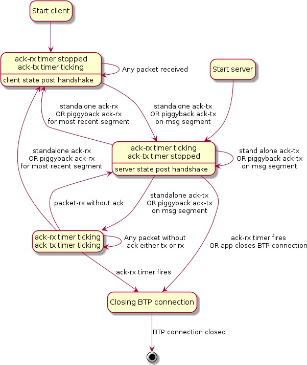
Figure 28. State diagram for BTP session post-establishment
Parameters and Constants
Table 32, “Glossary of constants” is a glossary of constants used in this chapter, along with a brief description and the default for each constant.
Table 32. Glossary of constants
Constant Name
Description
Default
BTP_CONN_RSP_TIMEOUT
The maximum amount of time after sending a BTP Session Handshake request to wait for a BTP Session Handshake response before closing the connection.
5 seconds
BTP_ACK_TIMEOUT
The maximum amount of time after receipt of a segment before a stand-alone ACK must be sent.
15 seconds
BTP_CONN_IDLE_TIMEOUT
The maximum amount of time no unique data has been sent over a BTP session before the Central Device must close the BTP session.
30 seconds
Bluetooth SIG Considerations